


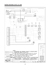
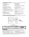
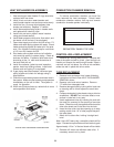
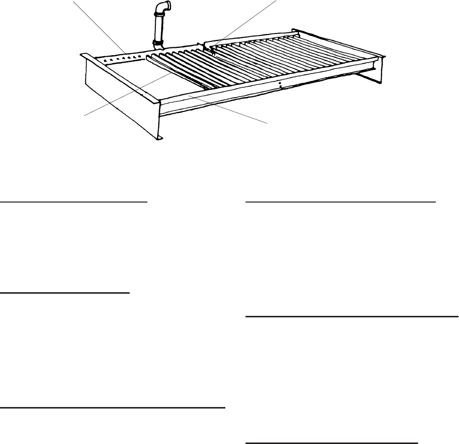
COMBINATION FLAME SENSOR/
IGNITOR AND PILOT BURNER LOCATION
TYPICAL BURNER TRAY ILLUSTRATED
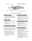
BURNER TRAY REMOVAL
1. Shut-off power and gas supply to the heater.
Disconnect union(s) and pilot tubing, then
loosen and remove burner hold-down screws.
2. Disconnect wires at gas valve and slide burner
drawer out.
GAS VALVE REMOVAL
1. Shut-off gas supply to the heater. Remove gas
piping to gas valve inlet.
2. Disconnect wires, pilot tubing and bleed line, if
required.
3. Turn vertical gas pipe from manifold slightly and
unscrew gas valve.
4. Reverse above procedure to re-install.
MAIN BURNER AND ORIFICE REMOVAL
1. Remove screws and burner hold-down bracket.
NOTE: If the heat exchanger is sooted badly, the
burner hold-down bracket and spacer can become
distorted from direct flame impingement and this usu-
ally necessitates replacement of these parts.
2. Lift burners from slotted spacer and slide from
orifices. Clean with a wire brush.
3. Orifices usually do not need to be replaced.
To clean, run either copper wire or wood
through orifice. Do not enlarge hole. To
remove orifice, use a socket wrench and
remove the manifold. DO NOT overtighten
when reinstalling.
PILOT REMOVAL AND CLEANING
1. Disconnect pilot tubing at pilot and sensor/igniter
wire. Remove screws holding pilot bracket to
burner tray.
2. Remove pilot and bracket, clean pilot of debris,
small bugs, etc., with wire or small brush.
3. Replace pilot, pilot tubing, sensor ignition wires
and check for leaks.
HIGH LIMIT OR TANKSTAT REMOVAL
1. Turn off electrical power.
2. Remove front inspection panel.
3. Remove wires to high limit and loosen screws
holding high limit to cabinet.
4. Remove wedge clip holding sensing bulb in
control well.
5. Remove high limit and install a new one.
6. Check control operation before leaving job.
HEAT EXCHANGER REMOVAL
1. Shut water, gas and electricity off, close valves
and relieve pressure, remove relief valve.
2. Remove side inspection panels.
3. Remove top holding screws.
4. Remove draft diverter, lift and remove top and
flue collector on stack type models. Remove
inspection panels.
5. Loosen bolts and disconnect flange nuts on
in/out header, loosen union (s) at gas
pipe, and slide heater away from piping until
studs clear the heater.
6. Remove heat exchanger corner brackets.
7. Remove combustion chamber clips at the four
corners of the heat exchanger.
8. Lift heat exchanger straight up using caution not to
damage refractory.
BURNER ORIFICES
BURNERS
BURNER HOLD-DOWN LOCATION
49