


(d) Place in operation the appliance being inspected.
Follow the lighting instructions. Adjust thermostat
so appliance will operate continuously.
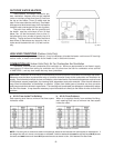
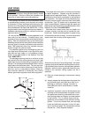
(e) Test for spillage at the drafthood relief opening
after 5 minutes of main burner operation. Use the
flame of a match or candle, or smoke from a
cigarette, cigar or pipe.
(f) After it has been determined that each appliance
remaining connected to the common venting sys-
tem is venting properly, return doors, windows,
exhaust fans, fireplace dampers and any other gas
burning appliance to their previous conditions of
use.
15
(g) Any improper operation of the common venting
system should be corrected so that the installation
conforms with the latest edition of the National Fuel
Gas Code, ANSI Z223.1. When re-sizing any
portion of the common venting system, the com-
mon venting system should be re-sized to
approach the minimum size as determined using
the appropriate tables in Part 11 of the National
Fuel Gas Code, ANSI Z223.1.
For special venting applications that require reduced
vent sizes and through-the-wall venting, the Type D
Induced Draft Assembly can be used. Consult the
factory or your local Raypak representative.
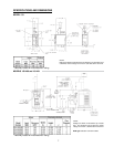
MODELS 133 THROUGH 180
(WHERE REQUIRED)
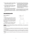
LOCATION
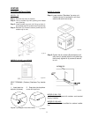
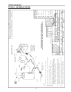
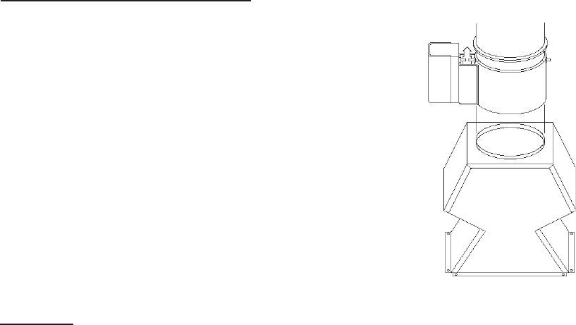
The vent damper must be located in the vent so
that it serves only the appliance for which it is intended.
If improperly installed, a hazardous condition, such
as an explosion or carbon monoxide poisoning, could
result. Make certain that it is mounted in an accessible
location at least 6 in. from any combustible material or
the heat exchanger and that the position indicator is in
a visible location.
The vent damper must be installed after the appli-
ance drafthood, as close to the drafthood as practi-
cable, and without modification of the drafthood.
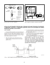
Fig. # 8182.0
WARNING: Do not use thermally actuated vent dampers on modulating heater. To do so, may result in
asphyxiation. Use only a mechanically actuated vent damper device that is electrically interlocked with the
modulating heater operation.
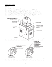
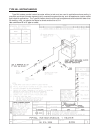
MOUNTING
On vertical vents, the vent damper may be mounted with the actuator in any position. On horizontal vents,
do not mount the actuator either directly above or directly below the vent pipe; mount the vent damper actuator
to the side of the vent.
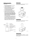
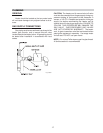
The vent damper is set up for a continuous pilot system. If the vent damper is installed on an Intermittent
Pilot or Direct Spark Ignition equipped system, the energy savings of the vent damper can be improved by
plugging the hole in the vent damper blade using the knockout plug, Part No. 105612R, provided in the parts
envelope.
DO NOT plug the hole if installing the vent damper on a continuous pilot system as this will create a hazardous
condition.
VENT DAMPER INSTALLATION