


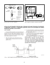
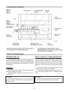
OPERATING CONTROLS
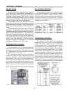
On models 514-1826, models with mechanical
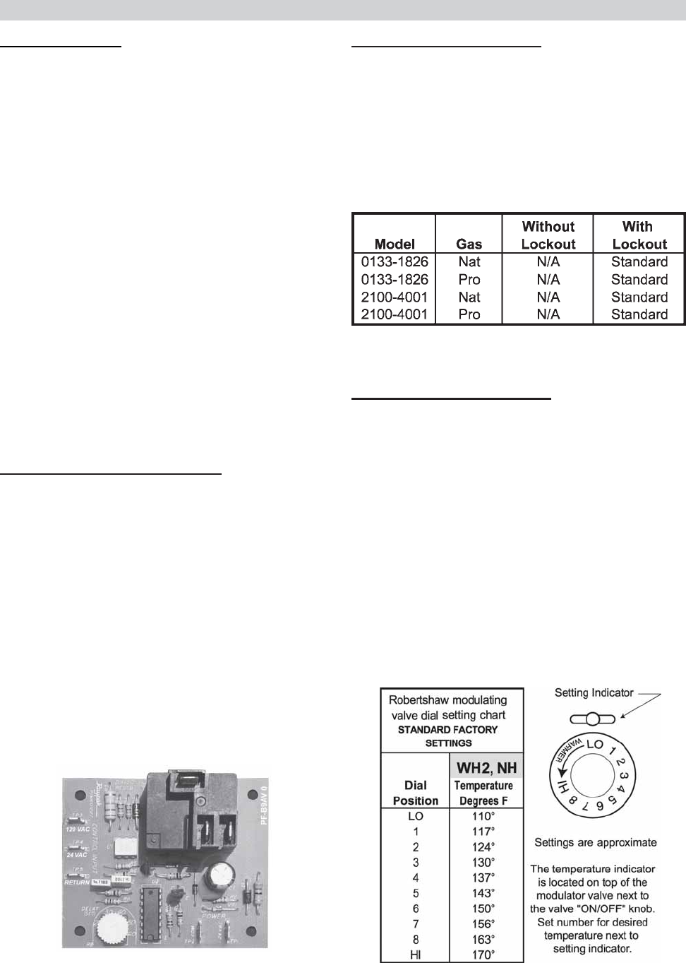
modulating controls have one or more Robertshaw
Unitrol 7000 Series hydraulic snap on thermostatic
combination gas valves. These valves have the pres-
sure regulator and 24-volt operator built-in. The hy-
draulic actuator will throttle the heater input to adjust the
firing rate and meet the required load. This, in effect,
prevents costly fuel consumption, as compared to an
on-off cycling heater. The valve has a remote capillary
bulb immersed in a well, at the header outlet, to main-
tain a constant outlet water temperature. When mul-
tiple valves are furnished, they can be staged to give
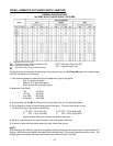
greater flexibility of control. Standard factory setting is
at position 5. Consult the dial setting tag attached to the
control for your desired temperature. See chart below.
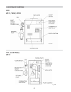
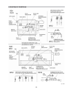
CONTROLS - GENERAL
24
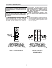
ELECTRONIC IGNITION
The intermittent ignition device conserves energy
by automatically extinguishing the pilot when desired
temperature is reached. When additional heat is
needed, the pilot re-ignites electrically, eliminating the
fuel costs of maintaining a constant pilot. To assure
safe operation, the gas valve cannot open until the pilot
relights and is confirmed.
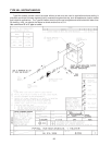
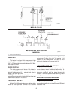
RELIEF VALVE
A new combination temperature and pressure
(T&P) relief valve, complying with the Standard for
Relief Valves and Automatic Gas Shut-Off Devices for
Hot Water Supply Systems, ANSI Z21.22, must be
installed in the opening provided on top of the storage
tank at the time of installation. No valve is to be placed
between the relief valve and the storage tank.
The pressure rating of the relief valve must not
exceed the 160 maximum working pressure indicated
on the water heater rating plate. The BTUH rating of the
relief valve must not be less than the BTUH input of the
heater.
Connect the outlet of the relief valve to a suitable
open drain. The discharge line must pitch downward
from the valve to allow complete draining (by gravity) of
the relief valve and discharge line. The discharge line
should be no smaller than the outlet of the valve. The
end of the discharge line should not be threaded or
concealed, and should be protected from freezing. No
valve of any type, restriction or reducer coupling,
should be installed in the discharge line. Local codes
shall govern installation of the relief valve.
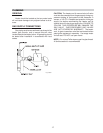
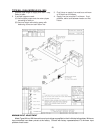
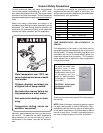
ECONOMASTER CONTROL
The Economaster II is an electronic device that
allows the operator to set the desired time for the pump
to run after the heater shuts off. The time is factory-set
at 7 minutes and it can be re-adjusted in the field
anywhere from 3 to 10 minutes.
In a conventional system, when the aquastat is
satisfied, the main gas valve closes, but the pump
continues operating. With the energy-conserving
Economaster II, the heater pump is programmed to
continue running for an optimum period of time in order
to absorb the residual heat from the combustion cham-
ber and use it in the system. The pump then shuts off
until the next call for heat is received from the aquastat.
NOTE: Pump will come on when power is first applied
to the heater.
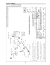
Fig# 9331
Fig # 9330.1