


March 2, 2007
7033-277C
Page 7
3100 Wood Stove Series (ACC)
R
Exterior conditions such as roof line, surrounding trees,
prevailing winds and nearby hills can influence stove
performance. Your local dealer is the expert in your geographic
area and can usually make suggestions or discover solutions
that will easily correct your fl ue problem.
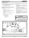
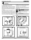
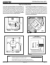
D. Flue Draft Considerations
Location of the appliance and chimney will affect perfor-
mance. As shown in Figure 6.1 on page 6 the chimney
should:
• Be installed through the warm space enclosed by the
building envelope. This helps to produce more draft,
especially during lighting and die down of the fi re.
• Penetrate the highest part of the roof. This minimizes
the affects of wind turbulence and down drafts.
• Consider the appliance location in order to avoid
fl oor and ceiling attic joists and rafters.
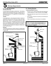
E. Venting Systems
The venting system consists of a chimney connector (also
known as stove pipe) and a chimney. These get extremely
hot during use. Temperatures inside the chimney may
exceed 2000°F (1100°C) in the event of a creosote fi re. To
protect against the possibility of a house fi re, the chimney
connector and chimney must be properly installed and
maintained. An approved thimble must be used when a
connection is made through a combustible wall to a chimney.
A chimney support package must be used when a connection
is made through the ceiling to a prefabricated chimney.
These accessories are absolutely necessary to provide
safe clearances to combustible wall and ceiling material.
Follow venting manufacturer’s clearances when installing
venting system.
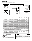
T
o be sure that your appliance burns properly, the chimney
draft (static pressure) should be approximately -.04 inch water
column (W.C.) during a low burn and -.10 inch W.C. during a
high burn, measured 6 inches (152mm) above the top of the
appliance after one hour of operation at each burn setting.
NOTE: These are guidelines only, and may vary somewhat
for individual installations.
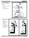
F. Tools And Supplies Needed
Before beginning the installation be sure that the following
tools and building supplies are available.
Reciprocating saw
Pliers
Hammer
Phillips Head Screwdriver
Flat Blade Screwdriver
Plumb Line
Level
Tape Measure
Framing Material
Hi-Temp Caulking Material
Gloves
Framing Square
Electric Drill & Bits (1/4”)
Safety Glasses
1/2 in. - 3/4 in. length, #6 or
#8 self drilling screws (need 3
per pipe section connection)
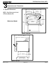
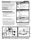
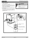
G. Inspect Appliance & Components and
Pre-Use Check List
1. Place the appliance in a location near the fi nal
installation area and follow the procedures below:
2. Open the appliance and remove all the parts and
articles packed inside the Component Pack. Inspect
all the parts and glass for shipping damage. Contact
your dealer if any irregularities are noticed.
3. All safety warnings have been read and followed.
4. This Owner’s Manual has been read.
5. Floor protection requirements have been met.
6. Venting is properly installed.
7. The proper clearances from the appliance and chim-
ney to combustible materials have been met.
8. The masonry chimney is inspected by a professional
and is clean, or the factory built metal chimney is
installed according to the manufacturer’s instruc-
tions and clearances.
9. The chimney meets the required minimum height.
10.
All labels have been removed from the glass door.
11. Plated surfaces have been wiped clean, if appli-
cable.
12. A power outlet is available nearby if installing
optional blower assembly.
WARNING
• Do NOT connect this unit to a chimney fl ue
servicing another appliance.
• Do NOT connect to any air distributon duct
or system.
May allow fl ue gases to enter the house.
Asphyxiation Risk.
Inspect appliance and components for damage.
Damaged parts may impair safe operation.
WARNING
• Do NOT install damaged components.
• Do NOT install incomplete components.
• Do NOT install substitute components.
Report damaged parts to dealer.
Fire Risk.