


Adjustment
5
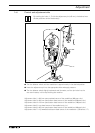
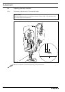
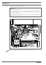
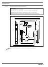
1.05 Control and adjustment aids
By marking the holes 1 - 7 with the adjustment pin (ø 5 mm), the desired nee-
dle bar positions can be fi xed exactly.
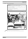
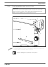
● Turn the balance wheel until the needle bar is approximately in the desired position.
● Insert the adjustment pin into the appropriate hole and apply pressure.
● Turn the balance wheel slightly backwards and forwards, until the pin locks into the
rear crank recess, in this way blocking the machine.
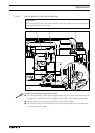
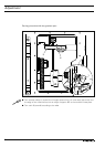
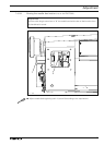
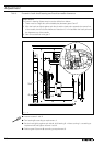
Adjustment hole 1 = 0.6 mm past top dead centre of the needle bar (0.6 past t.d.c.)
Adjustment hole 3 = 0.6 mm past bottom dead centre of the needle bar (0.6 past b.d.c.)
Adjustment hole 4 = 1.8 mm past bottom dead centre of the needle bar (1.8 past b.d.c.)
Adjustment hole 5 = top dead centre of the needle bar (t.d.c.)
Adjustment hole 6 = 4.0 mm past bottom dead centre of the needle bar (4.0 past b.d.c.)
Adjustment hole 7 = 1,5 mm before bottom dead centre of the needle bar ( 1,5 before u.T. )
Fig. 1 - 01
5
1
4
6
3
7