


6.5 Replacing Battery Pack.............................................................................................................................................20
6.6 Replacing Internal Pump...........................................................................................................................................20
6.7 Replacing Sensors ....................................................................................................................................................21
7.0 Instrument Information.............................................................................................................................. 22
7.1 Replacement Parts List .............................................................................................................................................22
7.2 Target Specifications ................................................................................................................................................23
8.0 Default Alarm and Configurations............................................................................................................. 24
9.0 Flow Diagrams ........................................................................................................................................... 25
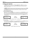
9.1 Basic Operation Menu ..............................................................................................................................................25
9.2 Standard Maintenance Menu.....................................................................................................................................26
9.3 Advanced Operation Menu .......................................................................................................................................27
9.4 Advanced Maintenance Menu, Software 4.94 version................................................................................................28
9.4 Advanced Maintenance Menu, Software 6.0 version..................................................................................................29
10.0 Troubleshooting....................................................................................................................................... 30
11.0 WARRANTY.............................................................................................................................................. 31
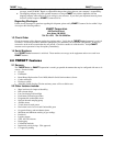
List of Figures and Tables
F
IGURE
1: F
RONT
V
IEW
.........................................................................................................................................................3
F
IGURE
2: S
ENSOR
V
IEW
.......................................................................................................................................................3
F
IGURE
3: T
OP
V
IEW
............................................................................................................................................................3
F
IGURE
4: B
OTTOM
V
IEW
......................................................................................................................................................3
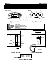
F
IGURE
5: M
AIN
G
AS
D
ISPLAY
..............................................................................................................................................3
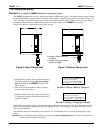
F
IGURE
6: I
NSERT
C
HARGE
J
ACK
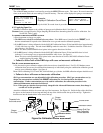
...........................................................................................................................................5
F
IGURE
7: R
EMOVE
C
HARGE
J
ACK
.........................................................................................................................................5
T
ABLE
1: B
ATTERY
L
IFE
.......................................................................................................................................................6
T
ABLE
2: P
ROGRAMMED
F
LAMMABLE
G
AS
C
OEFFICIENTS
.....................................................................................................8
F
IGURE
8
A
: C
ALIBRATION
S
HIELD
A
TTACHMENT
.................................................................................................................13
F
IGURE
8: V
ARIOUS
C
ALIBRATION
A
DAPTER
A
TTACHMENTS
...............................................................................................14
F
IGURE
9: R
EPLACING
B
ATTERY
P
ACK AND
I
NTERNAL
P
UMP
..............................................................................................20
F
IGURE
9
A
: R
EPLACING
I
NTERNAL
P
UMP FOR INSTRUMENTS WITH S
/
N
0699
AND BELOW
.......................................................20
F
IGURE
10: R
EMOVE SHORTING CLIP
...................................................................................................................................21
F
IGURE
11: R
EPLACING
S
ENSORS
.......................................................................................................................................21
T
ABLE
3: D
EFAULT
A
LARM
.................................................................................................................................................24
T
ABLE
4: D
EFAULT
C
ONFIGURATION
...................................................................................................................................24
T
ABLE
5: T
ARGET
M
ENU
Q
UICK
R
EFERENCE
.......................................................................................................................25
Reference Information:
N
OTE
: [important information about use of the instrument.]
C
AUTION
: [affects equipment – if not followed may cause damage to instrument, sensor etc…]
W
ARNING
:
[affects personnel safety – if not followed may cause bodily injury or death.]