


TARGET Series ENMET Corporation
13
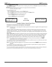
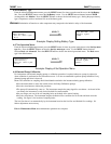
6.3.2 Zero Adjust
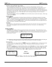
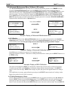
The calibration zero procedure is activated by pressing the SELECT button again. This starts a 30 second count down
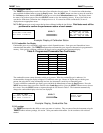
timer, at the end of which, the zero reading is stored in memory. The next screen displays the span gas concentration.
Example:
Display of Calibration Count Down
N
OTE
: The oxygen sensor requires only the initial 30 second clean air procedure.
6.3.3 Applying Span Gas
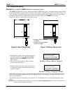
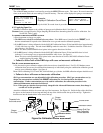
Attach the calibration adapter to the cylinder of span gas and calibration shield. See figure 8.
C
AUTION
: Some gas require that the Target Sampling Shield and flow demand regulator be used for calibration. See
Section 8.0, Table 3 and 4.
I
F A SENSOR IS INSTALLED IN
BRH L
OCATION
:
Place instrument on charge over night.
The BRH sensor should be calibrated before any others. If the BRH sensor is installed in the TARGET, it will
become contaminated if exposed to the combination or test gas and must be calibrated separately.
If the BRH sensor is being calibrated with the 04834-002 calibration fixture, fill the humidifier bowl approximately
1/3 full with clean, tap water. The tube should NOT go under the water line. No bubbles should be visible when
gas is flowing. See figure 8.
N
OTE
: The arrow on the humidifier bowl points in the opposite direction of airflow.
If the BRH sensor is being calibrated with the 04834-005 calibration fixture, fill the humidifier bowl to level
indicated. Use the storage case to support the humidifier while in use. See figure 8.
N
OTE
: The arrow on the humidifier bowl points in the same direction of airflow. 04834-005 calibration fixture
supplied starting November 2002.
Failure to follow both of the BRH steps will cause an inaccurate calibration.
F
OR
A
LL OTHER SENSORS INSTALLED
:
Use the reactive gases calibration adapter which does not have a humidifier bowl. For CO, O2, Methane sensor
calibration these sensors may be calibrated simultaneously or individually using the combination calibration gas and
reactive gases calibration adapter. See figure 8.
N
OTE
: When calibrating CO, O2 and CH4, with individual gas cylinders, the BRH calibration adapter should be used.
Failure to do so will cause an inaccurate calibration.
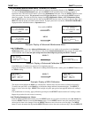
SPAN gas concentrations are not adjustable in this calibration procedure. SPAN gas concentrations are, by
design, the concentrations available with ENMET calibration kits. See Section 8.0 for the default
concentrations. If other concentrations are to be used for calibration, the calibration procedure in the
Advanced Maintenance menu must be followed.
N
OTE
: If the span gas value has been previously changed in the Advanced Maintenance menu, that change is
carried over to this procedure.
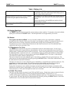
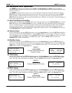
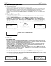
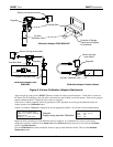
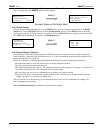
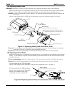
Attach the calibration shield to the sensor end cap of the instrument. See Figure 8A. Guide the flap of the shield into
the groove on the bottom of the end cap and bring the top of the shield towards the top of the end cap. Tighten the
thumb screw into the threaded hole in the sensor end cap.
Figure 8a: Calibration Shield Attachment
Sensor
End Cap
Groove
Calibration Shield
Sensor End Cap
with Calibration
Shield attached
TOP
BOTTOM
Thumb screw
Sensor
End Cap
Flap of Shield
Calibration Shield
Thumb screw
Threaded hole
for thumb screw
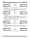
CAL: O2/CO/H2S/Mth
Sampling CLEAN AIR
MENU:Exit
Sample in 30 sec.
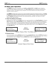
CAL: O2/CO/H2S/Mth
Apply Multi-Blend
SEL: frwd MENU:Exit