


9
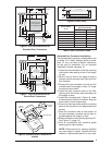
FLOOR CUT-OUT
FOR STANDARD
DUCT CONNECTORS
C
L
C
L
C
L
24"
23 1/4"
21 3/4"
14 1/2"
2 1/4"
2 3/4"
20"
CUT-OUT FOR
OPTIONAL
COOLING COIL
REAR WALL OF CLOSET OR ALCOVE
1 3/4"
2"
3/4"
C
L
C
L
C
L
10"
C
L
FURNACE OUTLINE
14 1/2"
ALT FUEL-LINE
ENTRY 1 1/4" Dia.
FURNACE
OUTER
DOOR
FUEL
LINE
1 3/4"
3/4"
1 7/8"
2 7/8"
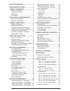
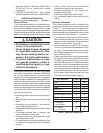
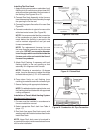
Figure 6. Cut-Out Dimensions for
Standard Duct Connectors
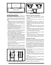
FLOOR
CUT-OUT FOR
ROUND DUCT
(14 1/4” DIAMETER)
C
L
C
L
C
L
C
L
24"
23 1/4"
21 3/4"
20"
CUT-OUT FOR
OPTIONAL
COOLING COIL
ALT FUEL-LINE
ENTRY 1 1/4" Dia.
FURNACE
OUTER
DOOR
REAR WALL OF CLOSET OR ALCOVE
FUEL
LINE
1 3/4"
2"
3/4"
C
L
C
L
10"
FURNACE OUTLINE
1 3/4"
10"
3/4"
1 7/8"
2 7/8"
C
L
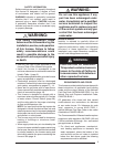
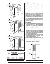
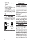
Figure 7. Cut-Out Dimensions for
Round Duct Connectors
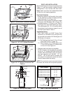
Bend tabs
up 90°
Mounting Plate
Duct
Connector
Connector
Tabs
Supply
Air Duct
Hole for
Gas Line
Wood Floor
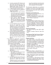
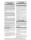
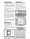
Figure 8. Standard Duct Connector In-
stalled
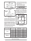
If Floor Cavity
“X” is:
Duct Connector
Type & Part Number
Standard Duct Round Duct
7/8” / (22) 901987A 904008
2” / (51) 901988A 904009
4-1/4” / (108) 901989A 904010
6-1/4” / (159) 901990A 904011
8-1/4” / (210) 901991A 904012
10-1/4” / (260) 901992A 904013
12-1/4” / (311) 901993A 904014
Note: Dimensions shown as Inches / (Millimeter)
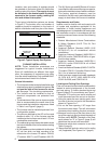
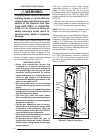
Table 3. Duct Connector Sizes
“X”
FLOOR OPENING
FLOOR
CAVITY
SUPPLY AIR DUCT
Figure 9. Floor Cavity
Standard Duct Connector Installation
The standard duct connector is designed for use
on ducts 12” in width. However ducts narrower
than 12” may not allow suffi cient clearances
for this type of installation. For an alternate
installation method, see page 10.
1. Center the duct connector in the fl oor opening
with bottom tabs resting on top of the supply
air duct.
2.
Mark the cut-out area on the supply air duct by
tracing around the connector tabs (Figure 8) of the
duct connector.
3. Remove the duct connector and cut out the
marked area of the supply air duct 1/4” larger
the actual cutout drawn.
4. Install the duct connector back in the fl oor
opening with the bottom tabs extending into
the supply air duct.
5. Install the mounting plate (Figure 8) under
the back side of the duct connector. Align the
screw holes in both components.
6. Secure the duct connector and the mounting
plate to the wood fl oor with appropriate size
screws.
7. Bend the connector tabs on the bottom of
the duct connector upwards and as tight as
possible against the supply air duct.
8. Bend both tabs on the mounting plate up 90°.
See Figure 10, (page 10)
9. Seal all connections with industrial grade
sealing tape or liquid sealant.
NOTE: Requirements for sealing ductwork
vary from region to region. Consult with local
codes for requirements specifi c to your area.