


16
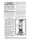
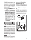
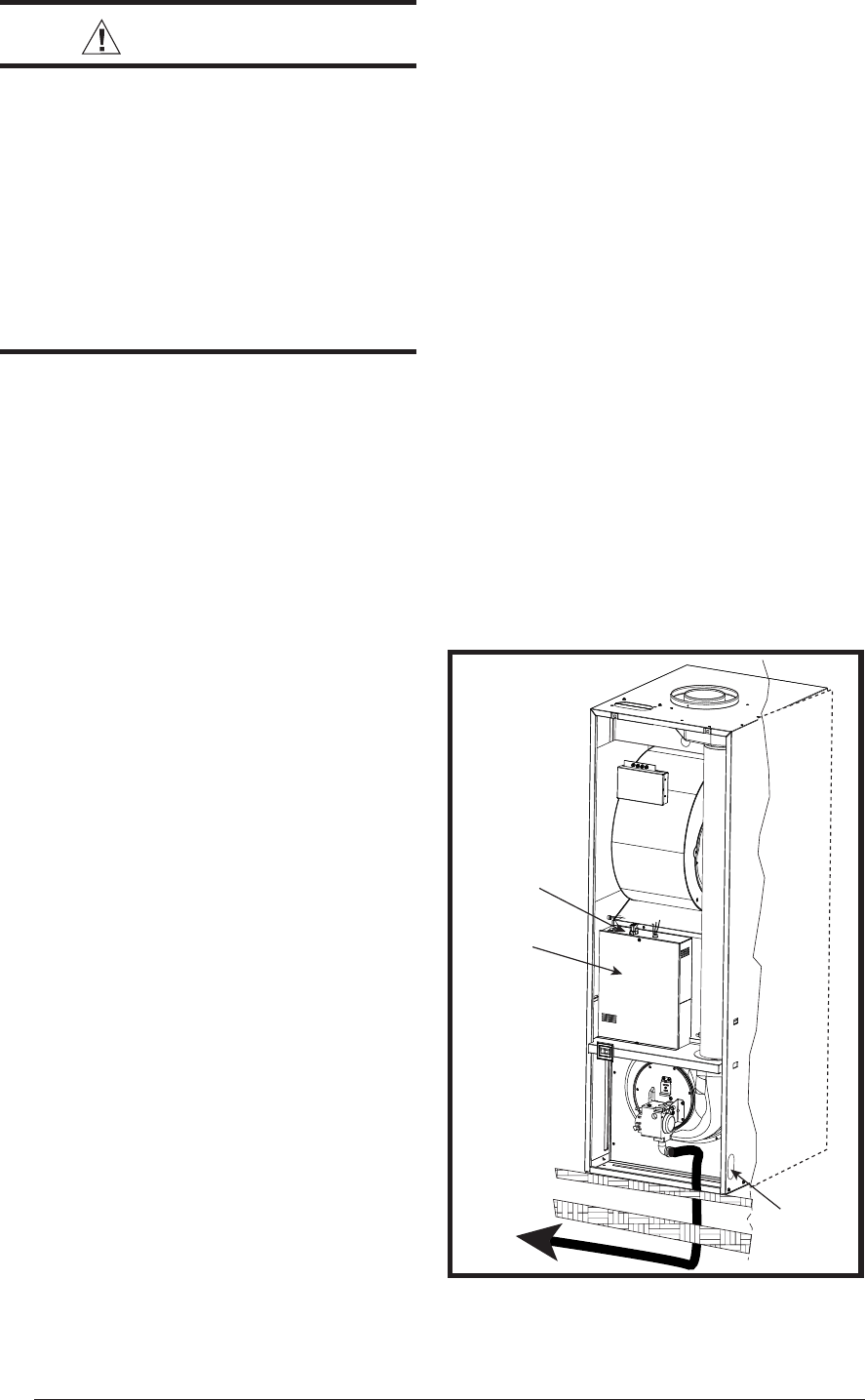
To Gas
Supply
Floor
Control
Panel
On-Off-Fan
Switch
Alt. Fuel
Line Entry
Floor Cavity
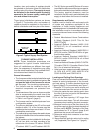
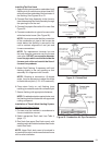
Figure 26. Typical Gas Piping
FUEL SUPPLY AND PIPING
WARNING:
All piping must conform with local
building codes, or in the absence
of local codes, with the most recent
edition of the National Fuel Gas
Code ANSI Z223.1 or (CAN/CGA
B149.1 or .2). Failure to follow all
safety warnings could result in
serious injury, death or property
damage.
This furnace may be installed with left or right
side gas entry. When connecting the gas supply,
provide clearance between the gas supply line
and the entry hole in the furnace casing to avoid
unwanted noise and/or damage to the furnace.
Typical gas service hookup for this furnace is
shown in Figure 26. Table 14 (page 37) lists
gas fl ow capacities for standard pipe sizes as a
function of length in typical applications based
on nominal pressure drop in the line.
IMPORTANT NOTES:
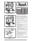
• Some local regulations require the
installation of a manual main shut-off
valve and ground joint union external to
the furnace (Figure 36). The shut-off valve
should be readily accessible for service
and/or emergency use. Consult the local
utility or gas supplier for additional
requirements regarding placement of the
manual main gas shut-off.
• Gas piping must never run in or through
air ducts, chimneys, gas vents, or elevator
shafts.
• Compounds used on threaded joints of gas
piping must be resistant to the actions of
-liquefi ed petroleum gases.
• The main gas valve and main power
disconnect to the furnace must be properly
labeled by the installer in case emergency
shutdown is required.
• Flexible gas connectors are not recom-
mended for this furnace but may be used
if allowed by local jurisdiction. Only new
fl exible connectors may be used. DO NOT
reuse old fl exible gas connectors.
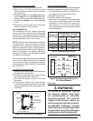
• A drip leg should be installed in the vertical
pipe run to the unit (Figure 36).
• All piping shall be black iron pipe, or
equivalently sized steel tubing. Internally
tinned copper tubing may be used for gas
supply systems.
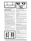
Fuel line installations other than typical
installations shown in Figures 26 and 27
(page 17) must comply with the fuel piping
provisions stated in the Federal Manufactured
Home Standard (H.U.D. TITLE 24, PART 280)
and the National Fuel Gas Code (ANSI-Z223.1/
NFPA-54).
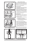
• Optional fuel inlet lines are available for all
gas furnace models to permit the addition of
a 1/2” F.P.T. shut-off valve above the fl oor.
NOTE: Shut-off valve must be designed and
listed for use with liquid petroleum (L.P. gas).
The gas supply to your home will either be Natural
Gas or L.P. (bottle gas). Your furnace is factory
equipped to operate on Natural Gas. If your gas
supply is L.P. (bottle gas), you must contact a
qualifi ed serviceman or gas supplier to convert
the furnace. Instructions for gas conversion are
listed on page 18. Factory installed orifi ce sizes
are listed in Table 10 (page 31).
For natural gas operation, the furnace is designed
for 7” W.C. inlet pressure. Pressure is reduced
to 3 1/2” W.C. by the pressure regulator in the
gas valve. The maximum inlet pressure for the
valve is 13” W.C.