


10
Alternate Attachment Method
The standard duct connector is designed for
use on ducts 12” in width. However if there is
insuffi cient clearance to bend the duct connector
tabs, this alternate attachment method may be
used.
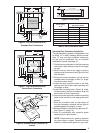
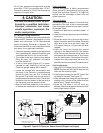
1. Score and cut the top of the supply air duct as
indicated in Option 1 or Option 2 (Figure 11).
With Option 1 choice, cut out the metal from
the shaded area.
2. Fold the two fl aps (Options 1 or 2) up to form
the opening for the duct connector.
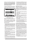
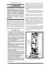
3. Install the duct connector with the bottom tabs
extending into the supply air duct.
4. Bend the tabs on the bottom of the duct
connector upwards and as tight as possible
against the supply air duct (Figure 12).
5. Form the fl aps (Options 1 or 2) up against the
duct connector as tight as possible.
6. Secure the duct connector fl aps to the supply air
duct with staples (3 minimum) or if a 2x block/
joist is not provided, use sheet metal screws
(2 minimum). NOTE: The duct connector tabs
may be attached to the air duct with sheet
metal screws or other suitable fasteners as
long as the duct connector and the air duct
are securely attached.
7. Seal all connections with industrial grade
sealing tape or liquid sealant.
NOTE: Requirements for sealing ductwork
vary from region to region. Consult with local
codes for requirements specifi c to your area.
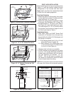
DUCT CONNECTOR
SUPPLY
AIR DUCT
BEND TABS TIGHTLY
AGAINST SUPPLY AIR DUCT
Figure 10. Duct Connector Tabs
Narrow
Duct
Narrow
Duct
Duct connector tabs
Staples or sheet metal screws
Duct
Flap
Narrow
Duct
Duct
Connector
Sheet metal
screws
Figure 12. Narrow Ducts
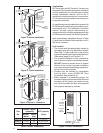
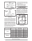
Round Duct Connector Installation
1. Apply a bead of caulking, mastic, or other
approved sealant around bottom side of
connector.
2. Install and center the duct connector in the
fl oor opening.
3. Install the mounting plate under the back side
of the duct connector. See Figure 13 (page 11).
NOTE: Align the screw holes in both
components.
4. Secure the duct connector and the mounting
plate to the wood fl oor with appropriate size
screws.
5. Connect the round supply duct to the underside
of the duct connector and secure them with
fi eld supplied sheet metal screws.
6. Seal all connections with industrial grade
sealing tape or liquid sealant.
NOTE: Requirements for sealing ductwork
vary from region to region. Consult with local
codes for requirements specifi c to your area.
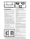
Figure 11. Narrow Air Duct Openings
OPTION 1 OPTION 2
Supply
Air Duct
Fold Flap Here
Fold Flap Here
Remove
this
Flap
Remove
this
Flap
Cut Here
Cut Here
Cut Here
Cut Here
Cut Here
Cut Here
Cut Here
Cut Here
Cut Here
Fold Flap Here
Fold Flap Here
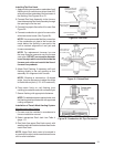
Installing The Furnace
Sides and back of the furnace may be enclosed
by wall framing such as in a closet or alcove. The
dimensions of the room or alcove must be able
to accommodate the overall size of the furnace
and the installation clearances outlined on page
2 and Figures 1 - 4 (page 6). The furnace shall
be appropriately connected to the supply and
return air distribution system as shown in Figures
14 & 15 (page 11).
1. Remove furnace outer door(s) and bottom fuel
line knockout.
2. Place furnace onto duct connector and center
with fl oor opening.
3. Slide onto mounting plate. (Bottom rear slots
on furnace should engage with mounting plate
tabs.)
4. Secure front with one (1) fastener at each
corner (Figures 14 or 15).
NOTE: Additional fasteners may be used at rear,
sides or through door frame, as desired, to secure
furnace to closet or alcove framing.