


12
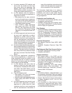
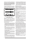
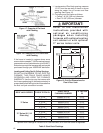
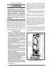
Figure 17. Example of Flat Jack
with Flashing
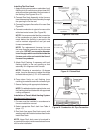
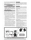
Figure 18. Example of 2½/12 Slant Jack
with Flashing
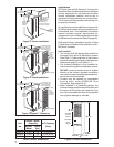
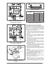
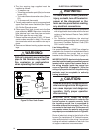
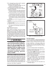
1. Locate center of Roof Jack opening, measure
13 1/2” from the rear wall of closet or alcove
along the center line of furnace and fl oor
opening. See Figure 19.
2. Cut ceiling and roof holes as follows:
• Ceiling = 8 3/4” (222 mm) diameter
• Roof = 9 3/8” (238 mm) diameter
IMPORTANT:
Refer to the installation
instructions provided with
optional air conditioning
packages when installing
furnaces with optional cooling
coil cabinet or with optional
C* series indoor coils.
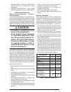
Table 5. Slant Deck Flashings
Optional Deck Flashings for Flat and 2.5/12 Pitch Roof Jacks. 4/12 Pitch Roof Jacks not applicable.
ROOF JACK SERIES IF ROOF PITCH IS:
SLANT DECK
FLASHING NUMBER
“X” FACTOR
IS:
“F Series
2” in 12” 903893 (2.5/12) 2-1/8”
2-1/2” in 12” 903893 (2.5/12) 2-1/2”
3” in 12” 903894 (3/12) 2-7/8”
3-1/2” in 12” 903894 (3/12) 3-1/4”
4” in 12” 903895 (4/12) 3-5/8”
“S” Series (2.5 / 12
Pitch only)
4-1/2” in 12” 903895 (2.5/12) 2-1/8”
5” in 12” 903895 (2.5/12) 2-1/2”
5-1/2” in 12” 903894 (3/12) 2-7/8”
6” in 12” 903894 (3/12) 3-1/4”
6-1/2” in 12” 903895 (4/12) 3-5/8”
CEILING
CUT-OUT FOR
FLUE AND
ROOF JACK
C
L
C
L
24"
20"
13 1/2"
REAR WALL OF CLOSET OR ALCOVE
10"
FURNACE
OUTER
DOOR
FURNACE OUTLINE
Figure 19. Cut-Out Dimensions for
Flue & Roof Jack
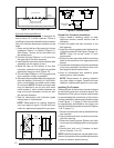
If the home is located in regions where snow
accumulation exceeds 7” (HUD snowload zones)
use an external roof jack extension (p/n 901937).
Extensions are optional accessories and may be
purchased through your NORDYNE distributor.
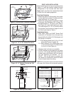
Locating and Cutting Roof & Ceiling Openings
DO NOT ALLOW DEBRIS TO FALL INTO THE
FURNACE. THIS COULD CAUSE UNSAFE
OPERATION AND VOIDS THE FURNACE
WARRANTY. Use the top cap that comes with
the furnace packaging (or alternate protector) to
prevent debris from falling into the furnace before
the fi nal roof jack connection is made