


6
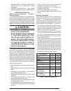
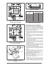
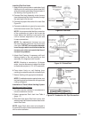
Figure 4. Overall Dimensions
“A”- 56"
23 3/4"
“B”- 76"
19 3/4"
“A” Model
w/o Coil
Cabinet
“B” Model
w/Coil
Cabinet
Applications
M1 Series gas and M5 Series oil furnaces are
listed direct vent (sealed combustion), downfl ow
heating appliances for manufactured (mobile)
homes, recreational vehicles, and for use in
residential/modular/commercial construction.
The furnace must be located so that venting can
be properly achieved.
Air conditioning may be added to structures with
M1/M5 series furnaces using air conditioning or
conventional units. This Installation Instruction
manual includes special requirements for
incorporation of air conditioning equipment to the
M1/M5 series of furnaces. See Tabel 12 (page 32).
Multi-speed blower assemblies shown in Table
2, have been certifi ed for fi eld installation in M1/
M5 Series furnaces.
Unit Location
• The furnace shall be appropriately located to
the supply and return air distribution system
(See Page 7). Sides and back of the furnace
may be enclosed by wall framing. See Minimum
Clearances (page 2) and Figures 1- 3.
• The furnace installation is only intended for
free air return through the furnace door louvers.
DO NOT connect a ducted return air system
directly to the furnace. Improper installation
may create a hazard and damage equipment,
as well as void all warranties.
• Furnace may be installed on combustible
flooring when using NORDYNE Duct
Connectors. See pages 9 & 10.
• When installed in a residential garage, the
furnace must be positioned so the burners and
the source of the ignition are located no less
than 18 inches above the fl oor and protected
from physical damage by vehicles.
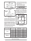
Table 2. Blower Assemblies
Part
No.
Blower / Motor
Assembly
A/C Capacity
(Tons)
Blower
Wheel
Motor
(Hp)
903773 10 x 8 1/4 2, 2½ & 3
903413 11 x 8 1/2 2, 2½, 3 & 4
903890 11 x 8 3/4 2, 2½, 3, 4 & 5
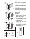
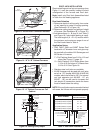
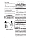
Removable access
panel should be
installed above
furnace door frame
to access roof jack
Nearest
Wall or
Partition
18"
(457 mm)
6" (152 mm)
Top Clearance
0" Side
Clearance
to Furnace
Cabinet
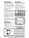
6" (152 mm)
Top Clearance
0" Side
Clearance
to Furnace
Cabinet
Provide min. 235
sq. in. (1516 cm )
open free area in
front or side wall
2
or
In closet
door
located
at top,
center
or bottom
CLOSET DOOR
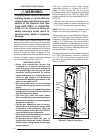
6" (152 mm)
Top Clearance
Provide min. 250
sq. in. (1613 cm )
open free area in
front or side wall
2
a fully
louvered
door may
be used
CLOSET DOOR
6"
(152 mm)
1"
(25 mm)
0" Side
Clearance
to Furnace
Cabinet
or
in closet
door
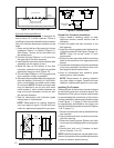
Figure 3. Special 1” Clearance
Figure 2. Closet Installation
Figure 1. Alcove Installation