


23
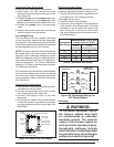
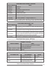
Table 7. Factory Combustion Air Settings
Model Nat. Gas LP Gas Oil
66,000 3.5 3.5 3.5
86,000 5.3 6 5
Combustion Air
In order for the fl ame to burn effi ciently, it must
receive adequate combustion air. The amount
of combustion air required varies according to
altitude, actual B.T.U. content of the fuel, gas
pressure, conversion to another gas and other
factors. The burner fl ame should be observed
and any necessary adjustments made before
the furnace is placed into service. See Table 7
for Factory Air settings.
CAUTION:
• Combustion air adjustment must
be made only by a qualifi ed tech-
nician. Improper air adjustment
may cause unsafe operation, ex-
plosion and/or fi re asphyxiation.
• If the input to the furnace is too
great because of excessive gas
pressure, wrong size nozzle or
orifi ce, high altitude, etc., the
burner fl ame will be sooty and
can produce carbon monoxide,
which could result in unsafe
operation, explosion and/or fi re
or asphyxiation.
The Smoke should be N0. 0 on the Bacharach
Scale, and 0 to 0.02 negative draft over fi re.
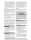
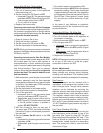
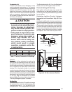
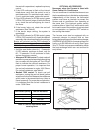
Electrode Setting (Oil Gun Only)
Poor ignition of the oil spray may result if the
electrodes are not adjusted as shown in Figure
34. Do not permit any electrodes to be grounded
to any surface.
Switching Ignition Control between
Interrupted and Intermittent Duty (Oil Gun
Only)
Honeywell and Beckett oil primary controls can
be switched between interrupted and intermittent
ignition control. To switch from interrupted duty
(Factory set) to intermittent duty, remove the blue
wire from the quick-connect terminal. Attach the
burner motor and igniter wire to the burner motor
(orange) control terminal by splicing or adding
tab adapters. Seal and isolate any bare wires.
5/32” GAP
ELECTRODE
NOZZLE
0-1/16”
5/16” ABOVE CL
1 1/8”
Figure 34. Oil Gun electrode Position
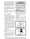
Gas Gun
Combustion air box adjustment is made to the
main burner by loosening the two lock nuts on
the plastic air shutter, located on the left side of
the burner blower housing. Air shutter adjustment
line is located on the same side of the blower
housing. Turn the plastic shutter to a smaller
number (counter clockwise) for less air to a larger
number (clockwise) for more air. Gently tighten
the lock nuts after completing the adjustment. For
best results, use instrument to measure between
8 - 9% CO
2
, after the combustion air has been
adjusted. Note: Do not over-tighten the lock nuts.
This may damage the plastic air shutter.
Oil Gun Only
It is recommended that the CO
2
and Smoke levels
be measured for maximum performance. CO
2
readings should be 10 - 11% for 66,000 BTUH
furnaces and 12 - 13% for 86,000 BTUH furnaces.