


11
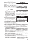
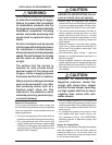
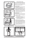
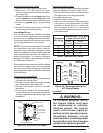
Figure 13. Round Duct Connector Installed
DUCT
CONNECTOR
MOUNTING
PLATE
SCREWS
FUEL
LINE
HOLES
14” SUPPLY
CONNECTION
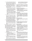
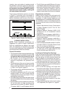
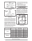
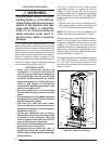
Table 4. Roof Jack Assemblies
SSAW
T
27
47 - 2
AW= ALL WEATHER
FLASHING
PITCH/12" RISE
0=FLAT
2=2.5/12
4=4/12
MIN. ADJ.
LENGTH
F = FLAT FLASHING
S = SLANT FLASHING
TYPE:
BLANK = NON-TRANSIT
T= TRANSIT MODE
MAX. ADJ.
LENGTH
FLUE STEEL TYPE
A= ALUMINIZED
S=STAINLESS
MODEL NUMBER
APPROX. LENGTH
BELOW FLASHING
(F,S)AW(T)1523-(0,2,4)(A,S) 15” - 23”
(F,S)AW(T)2135-(0,2,4)(A,S) 21” - 35”
(F,S)AW(T)2747-(0,2,4)(A,S) 27” - 47”
(F,S)AW(T)3563-(0,2,4)(A,S) 35” - 63”
(F,S)AW(T)5195-(0,2,4)(A,S) 51” - 95”
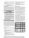
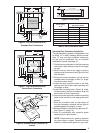
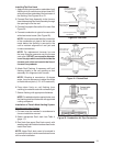
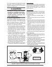
MTG. PLATE TABS
SLIDE FURNACE
ALL THE WAY BACK
ONTO MTG. PLATE
SUPPLY AIR DUCT
Knockout Over Holes
SECURE FURNACE
WITH 2 FASTENERS AT FRONT
CORNER HOLES
Figure 14. “A” & “B” Cabinet Furnaces
FUEL LINE HOLES
MTG. PLATE TABS
SLIDE FURNACE
BACK AGAINST
MTG. PLATE
SECURE FURNACE
WITH 2 FASTENERS
AT FRONT CORNER HOLES
SUPPLY
AIR DUCT
Figure 15. “A” Cabinet Furnace on Coil
Cabinet
ROOF JACK INSTALLATION
Required ceiling and roof cut-out openings (see
Figure 11) must be carefully located to avoid
misalignment of the furnace and Roof Jack.
Note: Install only Roof Jack Assemblies listed
in Table 4 on this heating appliance.
Roof Jack Selection
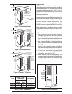
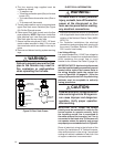
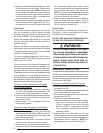
1. Determine depth of ceiling cavity from center
of roof opening to center of ceiling opening.
(See Dimension “A” in Figure 16.)
2. Determine ceiling height and subtract height
of furnace. (See Dimension “B” in Figure 16.)
3. Add dimensions A + B (and X from Table 5
and Figure 18 if slant deck fl ashing is used).
The total length of (A + B + X) must be within
the minimum and maximum range of one of
the Roof Jacks listed in Table 4.
Application Notes:
• FAW, FAWT, SAW and SAWT Series Roof
Jacks with a 5” diameter inner vent pipe may
be used with all models of M1 Series gas and
M5 Series oil furnaces.
F = Flat Flashing: fl exes from 0/12 to 1/12 roof
slope. See Figure 17 (page 12).
S = Slant Flashing: 2.5/12 Slope fl exes from
1/12 to 4/12 roof slope, 4/12 fl exes from
3/12 to 5/12. See Figure 18.
• Stainless steel roof jacks are available.
• M1/M5 furnaces may be used with roof jacks
as tall as 170” (except M1M 056 & M1B 066
models, which are limited to 120”). An internal
roof jack extension (p/n 901935 - 10”, p/n
903107 - 18”) can be used to increase roof
jack height. All connections inside the home
must be made below the ceiling.
NOTE: If the roof jack crown is covered or blocked
with snow, the furnace will not operate properly.
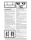
Figure 16. Ceiling Cavity Depth
ROOF JACK
SLANT DECK
FLASHING
PITCHED
ROOF
CEILING
CEILING
CAVITY
Roof
Opening
"X" (SEE TABLE 5)
Flue Pipe
Combustion Air Pipe
56" or 76"
Furnace
“A”
“B”