


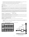

2. The boiler’s induced draft blower has a 3-in. outlet. A 3-in. X 4-in. increaser fitting is included in the parts bag. Locate increaser fitting
on outlet of induced draft blower and secure gastight with a bead of the factory-supplied silicone sealant. The increaser fitting is required
on this boiler for Category I venting, and 4 in. is the minimum permissible vent diameter. This does NOT imply that the vent connector
is intended to be 4-in. diameter pipe. The vent connector shall be sized according to the appropriate NFGC venting tables in the U.S.A. or
the NSCNGPIC in Canada, and may be required to be larger than 4-in. diameter.
NOTE: The boiler installation for chimney venting is not complete unless the 3-in. X 4-in. increaser fitting is located and secured.
3. These are energy-efficient boilers with a low stack or exhaust temperature.
4. If venting into masonry chimney without a liner, line chimney from top to bottom with either:
a. listed Type-B vent pipe
b. listed flexible vent liner
c. poured ceramic liner
5. Outside chimneys should not be used unless they are either:
a. enclosed in a chase
b. lined with Type-B vent pipe, listed flexible vent liner, or other certified chimney lining system
6. The vent connector from boiler to chimney should run as directly as possible with as few elbows as possible.
7. Where possible, it is recommended to common vent water heater and boiler. Consult the appropriate Vent Sizing Tables in either the NFGC
or NSCNGPIC for specific requirements of multiple appliance venting.
8. If boiler is the only appliance connected to vent, Type-B vent pipe is recommended for vent connector.
9. Slope pipe up from boiler to chimney not less than 1/4 in. per ft.
10. End of vent pipe must be flush with inside face of chimney flue. Use a sealed-in thimble for chimney connection.
11. The sections of vent pipe should be fastened with at least 3 sheet metal screws to make piping rigid. Use stovepipe wires to support pipe
from above.
12. Do not connect to fireplace flue.
13. Do not install a damper on this boiler.
PROCEDURE 2—MINIMUM VENT PIPE CLEARANCE
If vent pipe must go through a crawlspace, Type-B vent pipe should be used. Where vent pipe passes through a combustible wall or partition, use
a ventilated metal thimble. The thimble should be 4 in. larger in diameter than vent pipe.
If boiler is installed with single-wall vent, it must have a 6-in. clearance between its surface and any combustible material.
A new Type-B gas vent or flexible liner must be installed in accordance with instructions furnished with vent. Maintain clearances as specified
for vent pipe.
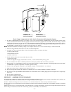
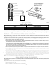
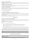
Check vent pipe to see if it is firestopped where it goes through floor or ceiling. It should have an approved vent cap with clearances from roof
shown in Fig. 5. If clearances are less than shown in Fig. 5, have vent checked by local authorities.
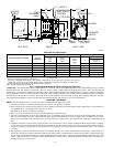
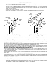
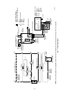
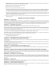
Fig. 4—Piping Arrangements for Boiler Used in Connection with Refrigeration System
A96141
VALVES A & B
OPEN FOR HEATING;
CLOSE FOR COOLING
TO SYSTEM
C
D
WATER
CHILLER
VALVES C & D
CLOSE FOR HEATING;
OPEN FOR COOLING
A
B
—8—