


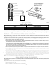
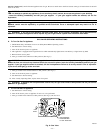
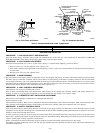
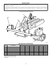
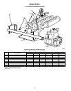
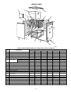
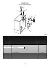


REPAIR PARTS
KEY NO. DESCRIPTION PART NO.
1 3/4-in. ASME Relief Valve 146-22-011
2 3/4-in. X 5-1/2-in. Nipple 146-07-040
3 Temperature-Pressure Gage—3-1/2-in. Shank 146-23-007
4 1-1/4-in. X 5-1/2-in. Nipple 146-07-019
5 1-1/4-in. X 3/4-in. X 1-1/4-in Tee 146-93-049
6 L8148A Combination Hi Limit and Relay Control 433-00-521
7 Taco Pump 007 146-26-047
* Grundfos Pump UP15-42F 146-26-045
8 1-1/4-in. Bent Return Nipple 146-07-004
9 Intermittent Pilot Control — S8600M 146-62-071
10 Induced Draft Blower and Gasket 433-00-511
11 Pressure Switch
2, 3, 4, 5 Section 146-55-006
6, 7 Section 146-55-005
* Rubber Tube (Blower to Pressure Switch) 146-29-003
* Rollout Switch 146-29-002
* 1-1/4-in X 3/4-in. Bushing 146-93-006
* Taco Flange Set 146-26-049
* Grundfos Flange Set 146-26-050
* AT 140C 24-v Transformer 146-62-080
* 1/4-in. Close Nipple 146-07-031
* 1/4-in. Coupling 146-93-054
* 400°F Black Silicone Rubber Adhesive Sealant (10.3 oz cartridge) 146-06-020
* 3-in. X 4-in. Increaser Fitting — Galvanized 146-28-012
* Not illustrated.
A99276
1
2
3
4
5
6
11
9
10
8
7
BOILER CONTROLS AND PIPING
—22—