


3. Boiler installation site experiences gusting or high winds. A power venter can help prevent the boiler from short cycling due to gusting or
high winds by providing vent exhaust pressures greater than the boiler’s induced draft blower alone.
4. When installer or homeowner prefers a negative pressure vent system instead of a positive pressure vent system.
5. May be more cost effective than stainless steel venting, particularly at longer vent lengths.
The Fields Controls power vent kit includes either a SWG-II-4HD or SWG-II-5 power venter, a MG-1 4-in. barometric draft controller, and the
CK-43D controls kit.
Confirm that installing a power venter is an option allowed by local codes. For installation information, follow specific Installation Instructions
provided with power venter kit.
NOTE: Although the power venter is equipped with its own fan, the fan on the boiler MUST remain in place and unaltered when a power venter
is used.
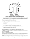
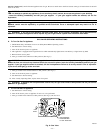
When sidewall venting, flue gases must be vented to a point in relation to the prevailing wind so they may freely disperse without being blown
back at the building causing discoloration, or into the building through doors or windows causing odors. Also, under certain conditions flue gases
will condense, forming moisture. In such cases, steps should be taken to prevent building materials at the vent terminal from being damaged by
the exhausted flue gas.
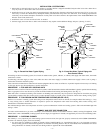
When installing single wall galvanized vent pipe for power venting, follow specific power venter Installation Instructions for layout, location of
barometric draft control, and termination connections. When joining and sealing single wall galvanized or Type-B vent piping, use RTV silicone
sealant with a minimum temperature rating of 400°F. For 3-in vent pipe runs, begin with the female end of vent pipe over boiler’s induced draft
blower outlet. For 4-in. vent pipe runs, begin with the 3-in. to 4-in. increaser fitting (included in boiler parts bag) over induced draft blower outlet.
Then follow by placing female end of 4-in. vent pipe over increaser fitting. When joining pieces of single wall galvanized vent pipe, a substantial
bead of silicone should be used at the joint to insure a leak-proof connection.
GAS SUPPLY PIPING
PROCEDURE 1—CHECKING GAS SUPPLY
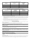
The gas pipe to boiler must be the correct size for length of run and for total Btuh input of all gas utilization equipment connected to it. See Table
5 for proper size. Be sure gas line complies with local codes and gas company requirements.
The boiler and its individual shutoff valve must be disconnected from gas supply piping system during any pressure testing of gas supply piping
system at test pressures in excess of 0.5 psig (3.5 kPa).
The boiler must be isolated from gas supply piping system by closing its individual manual shutoff valve during any pressure testing of the gas
supply piping system at test pressures equal to or less than 0.5 psig (3.5 kPa).
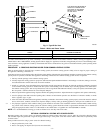
PROCEDURE 2—CONNECTING GAS PIPING
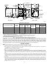
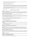
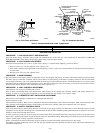
Refer to Fig. 6 for general layout at boiler. It shows the basic fittings needed. The gas line enters boiler from right side.
The following rules apply:
1. Use only those piping materials and joining methods listed as acceptable by the authority having jurisdiction or in the absence of such
requirements, by the NFGC. In Canada, follow the CAN/CGA-B149.1 and .2 Installation Codes for Gas Burning Appliances and
Equipment.
2. All pipe compound must be resistant to propane gas.
3. Install ground joint union in gas supply line between shutoff valve and boiler controls.
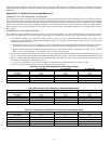
Table 5—Gas Pipe Sizes
NATURAL GAS
Length
of Pipe
(Ft)
Pipe Capacity—Btuh Input
Includes Fittings
1/2 in. 3/4 in. 1 in. 1-1/4 in.
20 92,000 190,000 350,000 625,000
40 63,000 130,000 245,000 445,000
60 50,000 105,000 195,000 365,000
PROPANE GAS
Length
of Pipe
Pipe Capacity—Btuh Input
Includes Fittings
Copper Tubing* Iron Pipe
(Ft) 5/8 in. 3/4 in. 1/2 in. 3/4 in.
20 131,000 216,000 189,000 393,000
40 90,000 145,000 129,000 267,000
60 72,000 121,000 103,000 217,000
* Outside diameter.
NOTE: The lengthof pipeor tubing shownshould bemeasured from gasmeter or
propane second-stage regulator.
Fig. 6—Gas Piping at Boiler
A95148
MANIFOLD
AUTOMATIC
GAS VALVE
MANUAL
SHUTOFF
VALVE
SEDIMENT TRAP
FLOOR LINE
GROUND JOINT
UNION
—10—