


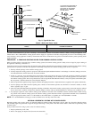

INSTALLATION—SYSTEM PIPING
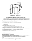
1. Place boiler in selected location (as close to chimney as possible). Boiler is shipped assembled. Only the relief valve with a drain line to
carry any water to a drain and a drain valve need to be installed.
2. Install relief valve on 3/4-in. pipe nipple in tapped opening in left end section. Connect a drain line of same pipe size (3/4 in.) to carry any
water away to a drain. No shutoff of any description shall be placed between safety relief valve and boiler, or on discharge pipes between
such safety valves and the atmosphere. Installation of safety relief valve shall conform to the requirements of the ANSI/ASME Boiler and
Pressure Vessel Code, Section IV.
3. Install drain valve on lower left side of boiler as marked.
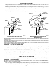
4. Connect supply and return lines to boiler. The connections may require certain additional fittings and parts. (See Fig. 2 and 4.)
If installing an entire new heating system, first install all radiation units (panels, radiators, or cabinets) and supply and return mains, then make
connections at boiler.
In connecting cold water supply to water valve, make sure that a clean water supply is available. When water supply is from a well or pump, a
sand strainer should be installed at pump.
A hot water boiler installed above radiation level must be equipped with a low water cut-off device. A periodic inspection is necessary as is flushing
of float-type devices per the manufacturer’s specific instructions.
PROCEDURE 1—FOR USE WITH COOLING UNITS
When this boiler is used in connection with refrigeration systems, it shall be installed so that the chilled medium is piped in parallel with the heating
boiler. Appropriate valves must be used to prevent the chilled medium from entering the heating boiler. (See Fig. 4.)
When this boiler is connected to heating coils located in air handling units where they may be exposed to refrigerated air circulation, the piping
system shall be equipped with flow control valves or other automatic means to prevent gravity circulation of boiler water during cooling cycles.
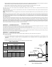
PROCEDURE 2—LOW DESIGN WATER TEMPERATURE SYSTEMS (BELOW 140°F)
If boiler is to be used in a heating system where design water temperatures below 140°F are desired (for example radiant floor heating), a 3-way
or 4-way mixing valve or suitable alternative is required to prevent low temperature return water from entering boiler. Follow mixing valve
manufacturer’s Installation Instructions.
The minimum design return water temperature to boiler to prevent condensation in boiler and venting system is 120°F. The minimum high limit
setting is 140°F.
CHIMNEY AND VENT PIPE CONNECTION
For boilers with connections to gas vents or chimneys, vent installations shall be in accordance with Part 7 NFGC, Venting of Equipment, in the
United States or Part 7 NSCNGPIC, Venting System and Air Supply for Appliances in Canada, and applicable provisions of local building codes.
PROCEDURE 1—CHECKING CHIMNEY
The chimney is a very important part of the heating system. It must be clean, the right size, properly constructed, and in GOOD CONDITION.
No boiler can function properly with a bad chimney.
1. Use local codes for installation or NFGC. In Canada, follow CAN/CGA-B149.1 or .2 Installation Codes. It is very important to properly
size the venting system for induced draft appliances. Consult the Vent Sizing Tables in Part 11 of the NFGC in the United States for correct
sizing information. In Canada, consult the Vent Sizing Tables in Appendix B of the NSCNGPIC.
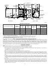
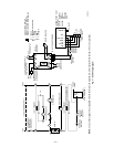
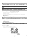
Fig. 2—Forced Hot Water Typical Piping
A95176
SUPPLY
MAIN
AIR
PURGER
FILTROL
TANK
LIMIT
CONTROL
RELIEF
VALVE
COLD WATER
INLET
AIR VENT
GAUGE
RETURN
LINE
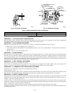
Fig. 3—Forced Hot Water Typical Piping with
Zone Control Valves
A96140
AIR
PURGER
FILTROL
TANK
LIMIT
CONTROL
RETURN
LINE
RELIEF
VALVE
COLD
WATER
INLET
AIR VENT
GAUGE
ELECTRIC
ZONE
VALVES
TO ZONE 1
SUPPLY MAIN
TO ZONE
2 SUPPLY
MAIN
—7—