


Canada Only—For altitudes in the range of 2000-4500 ft above sea level, boilers may be field equipped for use at high altitude by using a certified
field conversion kit. The change in main burner orifice size results in boiler’s input rating being reduced by 10 percent. The conversion shall be
carried out by a manufacturer’s authorized representative in accordance with the requirements of manufacturer, provincial or territorial authorities
having jurisdiction, and in accordance with the requirements of the CAN/CGA-B149.1 and CAN/CGA-B149.2 Installation Codes. The certified
field conversion kit includes a conversion data plate which must be attached to boiler adjacent to rating plate indicating that boiler has been
converted for high-altitude use. The conversion data plate must be filled in with the correct conversion information.
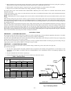
→ LOCATING THE BOILER
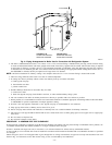
NOTE: This unit MUST be set on a concrete or other non-combustible material base or floor.
1. Select level location as centralized with piping system and as near chimney as possible.
2. Place crated boiler at selected location. Remove crate by pulling crate sides from top and bottom boards. When boiler is to be installed on
a combustible floor, a combustible floor base must be used.
This boiler must NOT be installed on carpeting.
3. Boiler is to be level. Metal shims may be used under base legs for final leveling.
4. The floor supporting boiler must be non-combustible. If it is combustible, place the boiler on a factory-approved combustible floor base.
We use a 2-in. Cladlite™ pad as a combustible floor base. These are available from your local supplier. Use a minimum 24-in. X 30-in.
pad for 2-5 section boilers and a minimum 30-in. X 30-in. pad for 6-7 section boilers. The boiler must be centered on combustible floor
base.
5. Additional clearances for service may exceed clearances for fire protection. Always comply with the minimum fire protection clearances
shown on the unit. An 18-inch clearance should be maintained on any side where passage is required to access another side for cleaning,
servicing, inspecting or replacement of any part that may need attention. An 18-inch clearance is recommended on the control side for
servicing.
6. Determine boiler room size. Rooms that are large in comparison with the size of boiler are defined as rooms having a volume equal to or
greater than 16 times the volume of the boiler. Where room ceiling height is greater than 8 ft, volume of room shall be figured on the basis
of 8 ft ceiling height. Determination of room size should be based on total volume of all gas fired equipment installed in that room. (See
Table 1.) Refer to Section 6.3 of NFGC, Central Heating Boilers and Furnaces for further information, including approved methods for
reducing clearances in large rooms.
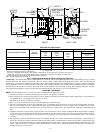
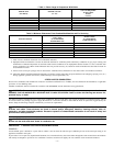
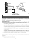
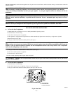
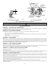
Fig. 1—Dimensional Drawing and Boiler Ratings and Capacities
Gas-Fired Hot Water Boilers
BOILER MODEL NUMBER*
NO. OF
SECTIONS
NATURAL AND PROPANE GAS† DIMENSIONS (IN.)
A.G.A.
Input
MBH
Heating
Capacity
MBH
Net
I=B=R
Rating
MBH
Width Vent Diameter
A
To Chimney
(Category I)
BW3AAN000042ABAA 2 42.5 36 31 11 4
BW3AAN000075ABAA 3 75.0 63 55 14-1/4 4
BW3AAN000112ABAA 4 112.5 94 82 17-1/2 4
BW3AAN000150ABAA 5 150.0 125 109 20-3/4 4
BW3AAN000187ABAA 6 187.5 155 135 24 4
BW3AAN000225ABAA 7 225.0 186 162 27-1/4 4
* Sixth position of Model No. indicates natural or propane gas usage: N = Natural Gas
P = Propane Gas
† Boilers are equipped for altitudes up to 2000 ft only.
U.S.A Only—For altitudes above 2000 ft, ratings should be reduced at the rate of 4 percent for each 1000 ft above sea level.
Canada Only—Boilers may be used at high altitude by using a certified field conversion kit, resulting in 10 percent derate.
Heating Capacity is based on Department of Energy (DOE) test procedure.
MBH—1000 Btuh (British Thermal Unit Per Hr)
A85084
29″
23″
25
1
⁄
4
″
23
1
⁄
4
″
5
5
⁄
8
″ 5
5
⁄
8
″
1
3
⁄
4
″
7″
A
GAS
VALVE
INT. PILOT
CONTROL
PRESSURE
SWITCH
BLOWER
VENT
CONNECTOR
COMBINATION
LIMIT & RELAY
CONTROL
1
1
⁄
4
″ SUPPLY
RELIEF
VALVE
BURNER
TEMP
PRESSURE
GAGE
1
1
⁄
4
″ RETURN
CIRCULATOR
LEFT SIDE RIGHT SIDEFRONT
—4—