


CHECKING AND ADJUSTING
PROCEDURE 1—GAS VALVE SAFETY SHUTDOWN TEST
With main burners firing, disconnect ignition cable from intermittent pilot control box. Gas valve should shut off main burners. TURN OFF
ELECTRIC POWER to boiler before reconnecting ignition cable to prevent electric shock.
PROCEDURE 2—PILOT BURNER ADJUSTMENT
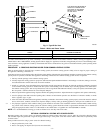
Pilot flame should surround 3/8- to 1/2-in. of pilot sensor. (See Fig. 9.) If flame needs adjusting, proceed as follows:
1. Remove screw cover over pilot adjusting screw. (See Fig. 10.)
2. Insert small screwdriver and adjust flame as needed. (See Fig. 9 and 11.) Turn screw counterclockwise to increase flame and clockwise to
decrease flame.
3. Replace screw cover over pilot adjusting screw.
PROCEDURE 3—MAIN BURNER(S)
The main burners do not require primary air adjustment and are not equipped with primary air shutters. Main burner flames should form sharp
blue inner cones in a softer blue out mantel, with no yellow. Puffs of air from blowing on the flame or stamping on the floor will cause the flames
to turn orange momentarily. This is not unusual. Remain still when observing the main burner flames. If the flame appearance is not correct, check
main burner orifices and the burner throat and flame ports for dust and lint obstruction. It may be necessary to remove the rollout shield to observe
the main burner flames. Replace rollout shield after observation. (See Fig. 11.)
PROCEDURE 4—LIMIT CONTROLS ADJUSTMENT
Instructions for each control are included with controls.
Table 6 shows recommended boiler water temperatures. These settings can be changed after becoming familiar with system operation. For
example, if system is not giving quite enough heat in very cold weather, the limit setting can be raised to 220°F.
PROCEDURE 5—THERMOSTAT HEAT ANTICIPATOR ADJUSTMENT
Instructions for final adjustment of thermostat are packaged with thermostat.
Set heat anticipator at 0.2.
Check thermostat operation. When set above temperature indicated on thermometer, boiler burners should ignite. Make certain thermostat shuts
boiler off when room temperature reaches selected setting and starts boiler operating when room temperature falls a few degrees.
PROCEDURE 6—SAFETY CONTROLS CHECK
After setting limit control to desired setting, check to see if it shuts off gas supply to burners. Set thermostat to call for heat and let boiler run until
temperature of water reaches limit setting. Gas valve should shut off and circulator should keep running until thermostat is satisfied or water cools
enough to restart burners through limit control.
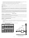
To check operation of contacts in pressure switch, disconnect rubber tubing (located between blower and pressure switch) from pressure switch
while boiler is operating. The burners should extinguish, and blower should keep running. When tubing is reconnected to pressure switch, ignition
sequence should begin, resulting in ignition of main burners.
Finally, set thermostat for desired temperature. Special conditions in home and location of thermostat govern this setting.
Safe lighting and other performance criteria were met with gas manifold and control assembly provided on boiler when boiler underwent tests
specified in ANSI Z21.13.
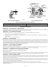
Fig. 9—Pilot Flame and Sensor
A95160
3
⁄8″ to
1
⁄2″
FLAME
ON SENSOR
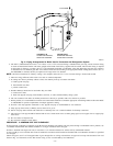
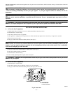
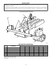
Fig. 10—Automatic Gas Valve
A95520
GAS CONTROL
KNOB SHOWN
IN "ON" POSITION
PILOT
ADJUSTMENT
(UNDER CAP
SCREW)
GAS
INLET
INLET
PRESSURE
TAP
WIRING
TERMINALS (3)
OUTLET
PRESSURE
TAP
GROUND
TERMINALS (2)
GAS
OUTLET
PILOT
OUTLET
OFF
ON
PRESSURE REGULATOR
ADJUSTMENT
(UNDER CAP SCREW)
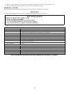
Table 6—Recommended Boiler Water Temperatures
TYPE OF HEATING UNIT LIMIT CONTROL SETTING
Standing Radiators 180°F
Baseboard and Convector Radiators 200°F
—16—
→