


24
W415-0607 / A / 01.18.08
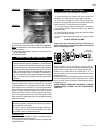
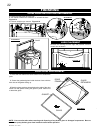
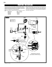
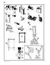
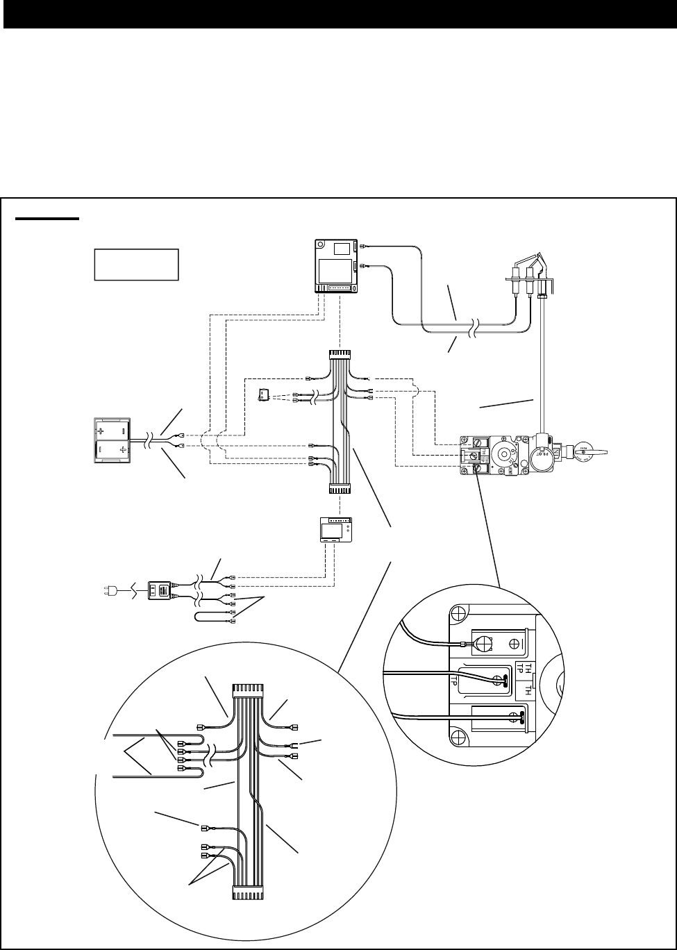
FIGURE 46
BATTERY
HOLDER
GAS VALVE
PILOT
ASSEMBLY
IGNITION
MODULE
PILOT
GAS LINE
Orange
(I)
[through
independent
conduit]
Yellow
(S)
[through
Gas line
conduit]
AC ADAPTOR
BATTERY
RELAY
Red (3 Volt)
Red
Black
WIRE
HARNESS
NOTE: WIRE TAGS
ARE BRACKETED
Brown
(SWI)
Black
(-)
Red
(+)
Green x2
(TH)
Orange x2
(THTP)
Black
Yellow
Blue
Black
(TP)
MODULE
PLUG
RELAY
PLUG
Black
Green
Orange
Black (12 Volt)
*
To Accent Light &
Night Light
TM
Switch
To Optional
Wall Switch
(GD-660)
MAIN
BURNER SWITCH
*
* See detail for optional
wall switch GD-660 wiring.
Main Burner Switch
WIRING DIAGRAM
The main burner on/off switch and Night Light
TM
switch is
located behind lower access panel. For ease of accessibility,
optional remote wall switches may be installed in a convenient
location for both burner and light operation.
The recommended maximum lead length depends on wire
size:
WIRE SIZE MAX. LENGTH
14 gauge 100 feet
16 gauge 60 feet
18 gauge 40 feet
Route 2-strand (solid core) wire through the electrical hole
located at the bottom left side of the unit. Connect the
wires from the wall switch to the two corresponding spade
connectors on the back of the on/off switches located behind
the lower access panel.