


17
W415-0607 / A / 01.18.08
SCREWS & WASHERS
4" COUPLER
SELF DRILLING
#8x1/2"
7" RIGID VENT
PIPE
SEALANT
HIGH TEMPERATURE
4" FLEXIBLE
VENT PIPE
7" RIGID
VENT PIPE
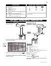
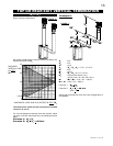
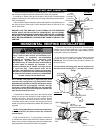
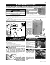
1. Attach the telescopic sleeve to the last section of 7" rigid vent pipe. Secure
with screws and high temperature sealant W573-0002 (not supplied).
2. Install the 4" fl exible vent pipe to the stove. Secure with 3 screws and fl at
washers. Seal the joint and screw holes using high temperature sealant W573-
0007 (not supplied).
3. Run a bead of high temperature sealant W573-0002 (not supplied) around
the inside of the air intake collar. Pull the telescopic sleeve a minimum 2" into
the air intake collar.
ENSURE THAT THE SEALANT IS NOT VISIBLE ON THE EXTERIOR
PIPES ONCE INSTALLATION IS COMPLETED. AN OPTIONAL
DECORATIVE BRASS BAND IS AVAILABLE FOR THIS USE. (STANDARD
WITH A GD-175 KIT AND GD-176). IN THE EVENT THAT THE VENTING
MUST BE DISASSEMBLED, CARE MUST BE TAKEN TO RESEAL THE
VENTING.
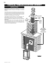
STOVE VENT CONNECTION
SELF DRILLING
#8x1/2"
SCREWS
AIR INTAKE
COLLAR
TELESCOPIC
SLEEVE
4” FLEXIBLE
VENT PIPE
7” RIGID
VENT PIPE
HIGH TEMPERATURE
SEALANT
FIGURE 23
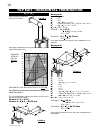
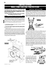
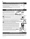
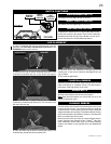
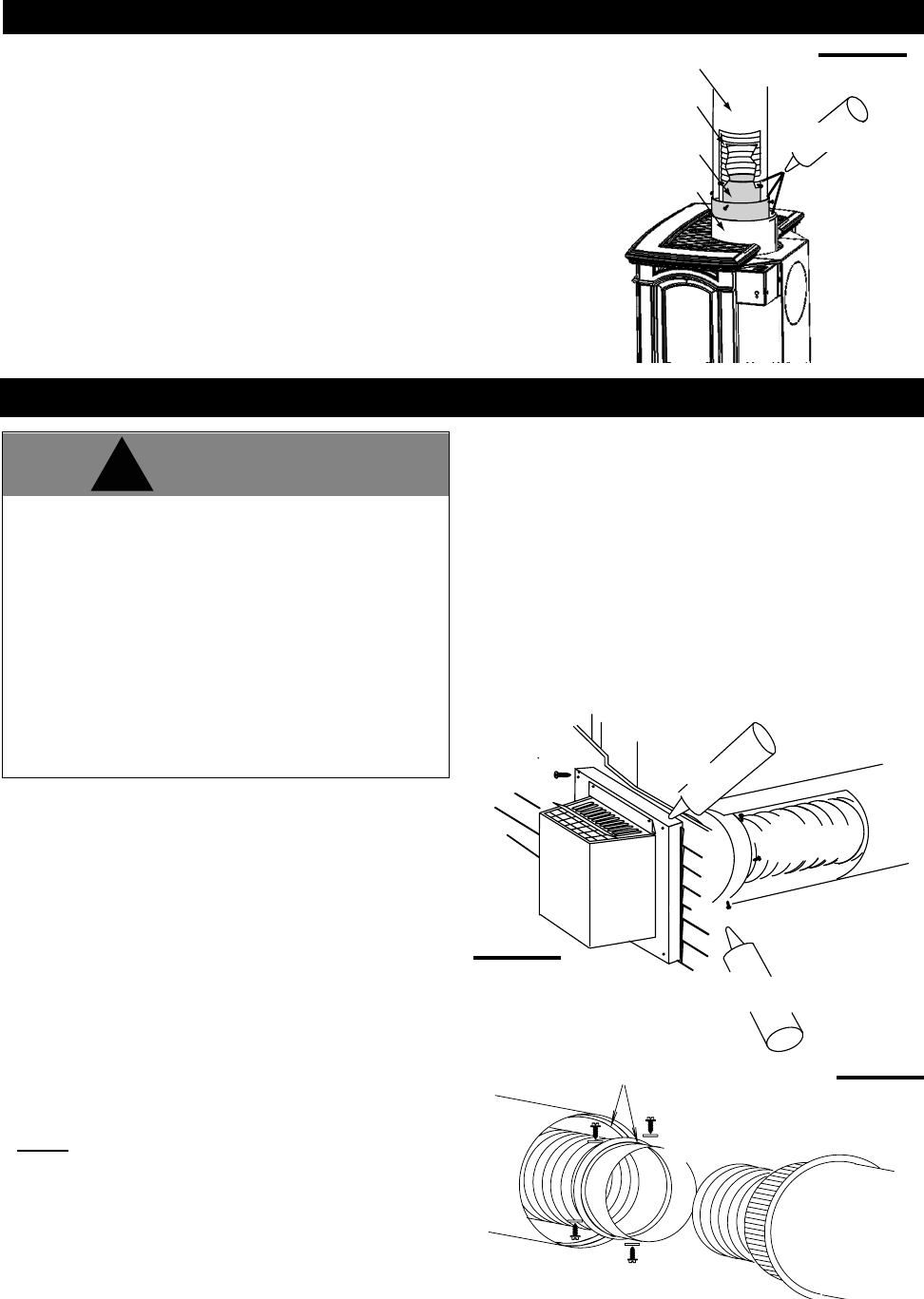
HORIZONTAL VENTING INSTALLATION
All 4" fl exible vent pipe and 7" rigid vent pipe joints
must be sealed using either high temperature sealant
W573-0002 (not supplied) or the high temperature sealant
W573-0007 Mill Pac (not supplied). However, the high
temperature sealant W573-0007 Mill Pac (not supplied)
must be used on the joint connecting the 4" fl exible vent
pipe and the exhaust fl ue collar.
1. Stretch the 4" fl exible vent pipe to the required length
taking into account the additional length needed for the
fi nished wall surface. Slip a minimum of 2" of the 4" fl exible
vent pipe over the inner sleeve of the air terminal. Secure
to the inner sleeve using 3 screws. Seal the joint and screw
heads using the high temperature sealant W573-0002 (not
supplied).
NOTE: If using pipe clamps to connect vent components,
3 screws must also be used to ensure the connection
cannot slip off.
2. Slip the fi rst section of 7" rigid vent pipe a minimum of
2" over the outer sleeve of the air terminal. Secure to the outer
sleeve using 3 screws. Seal the joint and screw heads using
high temperature sealant W573-0002 (not supplied).
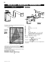
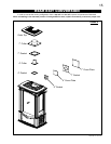
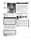
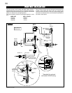
FIGURE 25
SCREWS
#10 x 2"
SEALANT
HIGH TEMPERATURE
2" OVERLAP
VENT PIPE
4"FLEXIBLE
CAULKING
VENT PIPE
7" RIGID
ATTE
NTION-
CHAUD
CAUTION - HOT
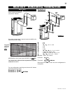
3. Insert the vent pipe through the fi restop / vent pipe shield.
Holding the air terminal (lettering in an upright, readable
position), secure to the exterior wall. Make weather tight by
sealing with caulking (not supplied).
4. If more than one length of vent pipe needs to be used
to reach the stove, couple them together as illustrated in
FIGURE 25. Seal the joints using the same procedure as
described above.
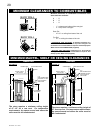
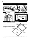
The air terminal mounting plate may be recessed into
the exterior wall or siding by 1½", the depth of the return
fl ange.
FIGURE 24
The vent system must be supported approximately
every 3 feet for both vertical and horizontal runs.
Use supports or equivalent non-combustible
strapping to maintain the 1" clearance from
combustibles. Use Wolf Steel Ltd. vent spacers
W615-0033 every 18" and at the start, middle and end
of each elbow to maintain the minimum 1 1/4"
clearance between the 4" flexible vent pipe and the
7" rigid vent pipe. These spacers must not be
removed. Use Wolf Steel Ltd. support ring assembly
W010-0370 or equivalent non-combustible strapping
to maintain the minimum clearance to combustibles
for both vertical and horizontal runs.
!
WARNING