


21
W415-0607 / A / 01.18.08
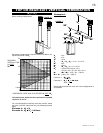
BLOWER INSTALLATION
ELECTRICAL INSTALLATION TO BE DONE BY A QUALIFIED INSTALLER and must be connected and grounded in
accordance with local codes. In the absence of local codes, use the current CSA C22.1
CANADIAN ELECTRICAL CODE in Canada
or the current ANSI/NFPA 70
NATIONAL ELECTRICAL CODE in the United States.
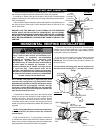
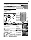
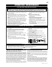
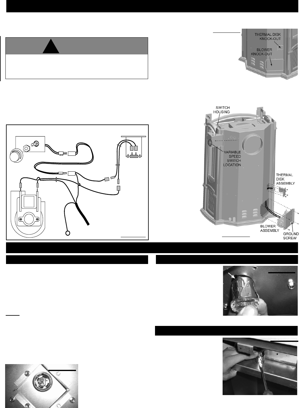
1. Break out the blower and thermal
disk knock-outs from the rear panel.
Figure 37a
2. Fish the wire extension through
the blower knock-out as shown
and connect to the prongs on the
thermodisc. Figure 37b
3. Ensure the thermodisc is touching the wall of the fi rebox. Secure the thermal disk assembly to the rear panel using
4 of # 8 screws supplied. Figure 37b
4. Connect the variable speed switch to the jumper wire (installed in the stove) located just inside the larger knock out
area. Figure 37b
5. Insert the blower assembly into the rear panel and secure using the
remaining #8 screws supplied.
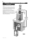
6. Remove the
switch housing,
connect the
variable speed
switch to the jumper
wire and mount the
switch to the side
of the housing.
Attach and secure
the variable speed
switch using the nut
provided. Reinstall
the switch housing.
Install the variable
speed switch
knob.
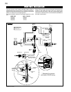
WHITE
RED
BLACK
GREEN
(GROUND)
THERMAL DISK
VARIABLE SPEED SWITCH
BLOWER
WIRE
EXTENSION
WIRE
HARNESS
(included in GS67 kit)
WHITE
TO
POWER
SUPPLY
LOCATED
IN WIRE
HOUSING
JUMPER WIRE (installed in stove)
GS67 WIRING DIAGRAM
VARIABLE
SPEED
SWITCH
KNOB
FIGURE 37a
FIGURE 37b
FIGURE 36
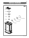
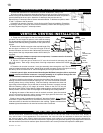
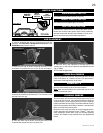
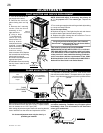
NIGHT LIGHT™ REPLACEMENT
1. Remove the door from
the fi rebox.
2. Run the wires up through
the lens hole.
3. Align key hole with lens
assembly.
4. Snap into place.
5. Replace light shields,
attach the wires and replace the door to the fi rebox.
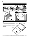
LENS ASSEMBLY INSTALLATION
1. Remove the front
door and top shield
from the firebox.
2. Compress the retainer
fi ns in with a screw driver
while pressing fi rmly on the
top of the light assembly.
3. Once all the retainer
fi ns are pushed in the lens
assembly will snap out of
place.
LENS ASSEMBLY REPLACEMENT
The GDS26 comes equipped with our “Night Light™”.
If in the event the lamp or lens needs to be replaced, follow
these instructions.
1. Turn off all electrical supply.
2. Remove the front and door from the fi rebox.
3. Unscrew the lens cover making sure the washer stays
in place.
Note: Do not handle the lamp (bulb) with bare fi ngers,
protect with a clean dry cloth.
4. The lamp will pull straight out of the socket. Replace with
Wolf Steel Ltd. parts only (W387-0006), as lamp and
lens are special "high temperature" products.
5. Replace lens with gasket, lense covers, attach wires to
quick connects and replace the door when fi nished.
THE FIREBOX MUST BE SEALED.
When re-assembling the
light assembly, care must
be taken. “Light Leakage”
from above the cast doors
may be noticed. The holes
in the lamp housing are
necessary for ventilation
and must not be covered.
BULB REPLACEMENT
FIGURE 38
FIGURE 40
KEY HOLE
FIGURE 39
This unit is equipped with a three prong grounding plug for your
protection against shock hazard and should be plugged directly into
a properly grounded three prong receptacle. Do not cut or remove
the grounding prong from this plug.
!
WARNING