


16
W415-0619 / B / 03.03.08
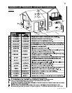
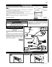
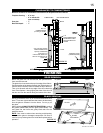
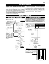
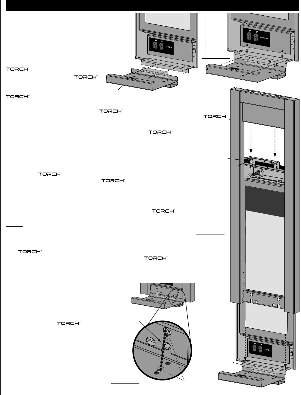
FIGURE 28
RECEIVING
SLOTS
DOOR STOP
CHAIN
FRAME/FRONT INSTALLATION
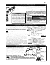
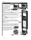
1. Align the two holes in the upper
portion of the hinge on the control door
to those in the bottom trim bracket,
secure using two of the #8 x 1/2” hex
head screws supplied. Figure 26
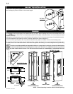
2. Install the top trim bracket to the
fi rebox using the three #9 - 14 x 1/2”
hex head screws supplied in the
manual baggie.
3. Rest the top lip of the
frame on the top trim bracket, and
the securing tabs at the bottom of the
frame on the bottom trim
bracket.
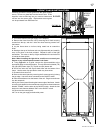
4. Align the two slots in the top of the frame with the two holes in the
top trim bracket and secure using the two #10 pan head screws supplied however
do not fully tighten to leave room for adjustment. Figure 27
5. Align the holes in the securing tabs at the bottom of the frame with
the holes in the bottom trim bracket and secure using the two remaining #8 x 1/2”
hex head screws, however do not fully tighten to leave room for adjustment.
Figure 27
6.
If required, the bottom trim bracket can be adjusted by loosening it’s securing
screws. Figure 27
7. Once the frame is perfectly square and the control door will close
without rubbing against the sides of the frame, tighten all screws.
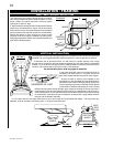
8. Open the control door.
9. Insert the door stop chain into the receiving slot in the control door.
Figure 29
10. Insert the door stop chain into the receiving slot in the frame so
that when fully open the control door has a clearance of 1/8” to the fi nished wall.
NOTE: In most cases, a count of 9 balls between receiving slots will give the
desired clearance. Figure 29
11. Close the control door.
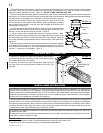
The frame has been designed to accommodate fi nished material
thicknesses of .500” - .750”. If it is necessary to pull the frame out to
the max. .750” the magnetic catch will need to be adjusted. Minor adjustment can
be made by removing shims from behind the magnet. Major adjustments can be
made by moving the magnet to the outside of the panel.
Adjustment may be required to accommodate
the door stop chain slack when the control door
is closed. The control door securing screws
can be loosened to allow adjustment. Before re-
tightening the screws ensure the control door is
still recessed into the frame at a similar
offset to the top trim piece.
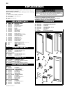
CONTROL DOOR
BOTTOM
TRIM
BRACKET
FIGURE 26
FIGURE 27
FRAME
TOP
TRIM
BRACKET
BOTTOM
TRIM
BRACKET
FIGURE 29