


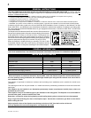
12
W415-0619 / B / 03.03.08
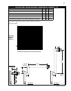
HIGH
TEMPERATURE
SEALANT
1
1
/
2
”
OVERLAP
SCREWS
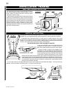
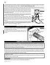
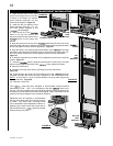
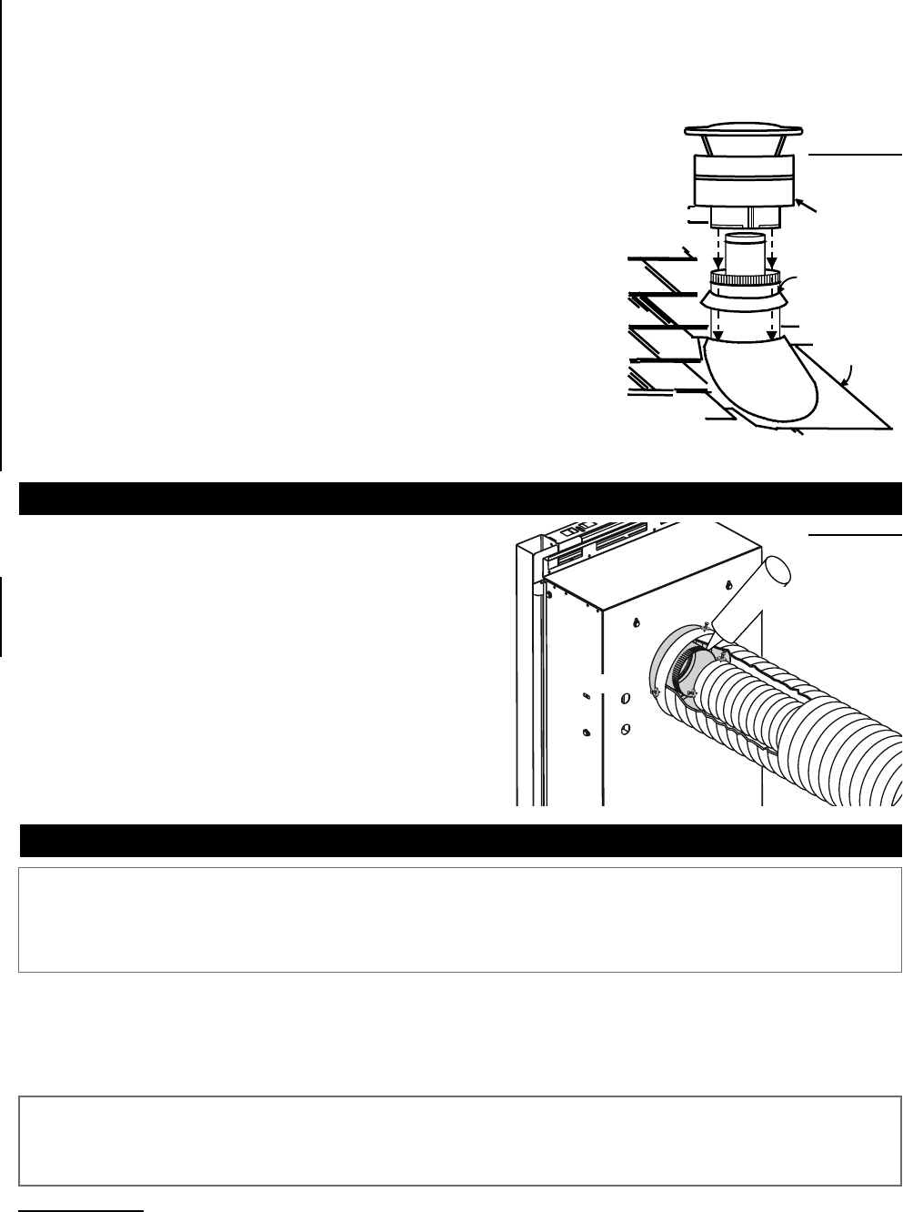
1. Install the 3” fl exible vent pipe to the fi replace. Secure with 3
screws and fl at washers. Seal the joint and screw holes using Mill
Pac sealant (W573-0007 not supplied).
2. Install the 5” fl exible vent pipe to the fi replace. Attach and seal
the joints using the high temperature sealant W573-0002 (not
supplied).
FIREPLACE VENT CONNECTION
FIGURE 15
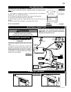
This Mobile/Manufactured Home Listed appliance comes factory equipped with a means to secure the unit. The fi replace is
equipped with two 1/4" diameter holes located in the front left and right corners of the base. For mobile home installations,
the fi replace must be fastened in place. Use #10 hex head screws, inserted through the holes in the base to secure. Always
turn off the pilot and the fuel supply at the source, prior to moving the mobile home. After moving the mobile home and prior
to lighting the fi replace, ensure that the logs are positioned correctly.
MOBILE HOME INSTALLATION
This appliance is certifi ed to be installed as an OEM (Original Equipment Manufacturer) installation in a manufactured
home or mobile home and must be installed in accordance with the manufacturer’s instructions and the Manufactured
Home Construction and Safety Standard, Title 24 CFR, Part 3280, in the United States or the Mobile Home Standard,
CAN/CSA Z240 MH Series, in Canada. This appliance is only for use with the type(s) of gas indicated on the rating plate.
A conversion kit is supplied with the mobile home appliance.
This appliance is certifi ed to be installed in an aftermarket permanently located, manufactured (mobile) home, where not
prohibited by local codes.
This fi replace is only for use with the type of gas indicated on the rating plate. This fi replace is not convertible for use with
other gases, unless a certifi ed kit is used.
Conversion Kits
The mobile home appliance is fi eld convertible between Natural Gas (NG) and Propane (LP).
To convert from one gas to another consult your Napoleon® dealer/distributor.
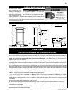
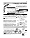
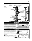
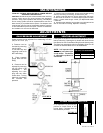
FIGURE 14
STORM
COLLAR
FLASHING
CAULKING
WEATHER
SEALANT
2”
AIR INLET
BASE
4. Thread the air terminal connector / vent pipe assembly down through the roof. The air terminal must be located vertically
and plumb. Attach the air terminal connector to the roof support, ensuring that the top of the air terminal is 16” above the
highest point that it penetrates the roof. Figure 12. DO NOT CLAMP THE FLEX VENT PIPE.
5. Remove nails from the shingles, above and to the sides of the chimney. Place the fl ashing over the air terminal connector
leaving a min. 3/4” of the air terminal connector showing above the top of the fl ashing. Slide the fl ashing underneath the sides
and upper edge of the shingles. Ensure that the air terminal connector is properly
centred within the fl ashing, giving a 3/4” margin all around. Fasten to the roof. Do
not nail through the lower portion of the fl ashing. Make weather-tight by sealing
with caulking. Where possible, cover the sides and top edges of the fl ashing with
roofi ng material. Figure 14.
6. Aligning the seams of the terminal and air terminal connector, place the terminal
over the air terminal connector making sure the vent pipe goes into the hole in the
terminal. Secure with the three screws provided. Figure 14.
7. Apply a heavy bead of weatherproof caulking 2" above the fl ashing. Note:
Maintain a minimum 2” space between the air inlet base and the storm collar. Install
the storm collar around the air terminal and slide down to the caulking. Tighten to
ensure that a weather-tight seal between the air terminal and the collar is achieved.
Figure 14.
8. If more vent pipe needs to be used to reach the fi replace, couple them together
as illustrated. The vent system must be supported approximately every 3 feet for
both vertical and horizontal runs. Use noncombustible strapping to maintain the
minimum 1" clearance to combustibles. Figure 11.