


11
W415-0619 / B / 03.03.08
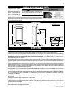
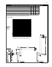
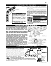
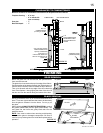
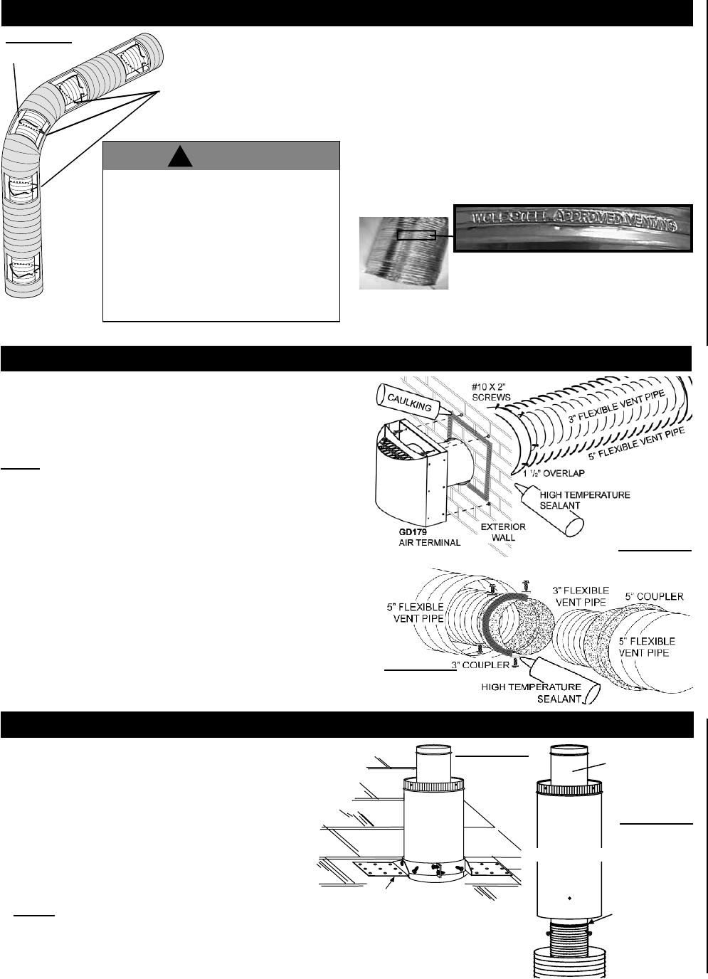
1. Stretch the 3” fl exible vent pipe to the required length taking into
account the additional length needed for the fi nished wall surface.
Apply a heavy bead of the high temperature sealant W573-0007
(not supplied). Slip the fl exible vent pipe a minimum of 2” over the
inner sleeve of the air terminal and secure with 3 - #8 screws.
NOTE: If using pipe clamps to connect vent components, 3
screws must also be used to ensure the connection cannot
slip off.
2. Using the 5” fl exible vent pipe, slide over the outer combustion
air sleeve of the air terminal and secure with 3 - #8 screws. Seal
using high temperature sealant W573-0002 (not supplied).
3. Insert the fl exible vent pipe through the fi restop maintaining the
required clearance to combustibles. Secure the terminal to the
exterior wall (lettering in an upright, readable position) and make
weather tight by sealing with caulking (not supplied).
4. If additional fl exible vent pipe is required, couple them together
as illustrated. The vent system must be supported approximately
every 3 feet for both vertical and horizontal runs. Use non-
combustible strapping to maintain the minimum 1” clearance to
combustibles from the fl exible vent pipe.
HORIZONTAL AIR TERMINAL INSTALLATION
FIGURE 10
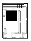
FIGURE 11
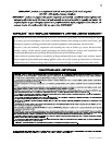
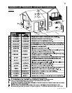
USING FLEXIBLE VENT COMPONENTS
USE ONLY WOLF STEEL LTD. 3” / 5” FLEXIBLE VENT COMPONENTS.
Use only approved fl exible vent pipe kits marked:
“Wolf Steel Approved Venting” as
identifi ed by the stamp only on the
5” fl exible vent pipe.
For safe and proper operation of the fi replace, follow the venting
instructions exactly.
All 3" fl exible vent pipe and 5" fl exible vent pipe joints may
be sealed using high temperature sealant W573-0002 (not
supplied) or the high temperature sealant W573-0007 Mill
Pac (not supplied). However, the high temperature sealant
W573-0007 Mill Pac (not supplied) must be used on the
joint connecting the 3" fl exible vent pipe and the exhaust
fl ue collar.
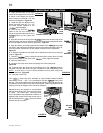
FIGURE 9
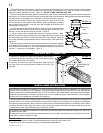
Four inches (4”) is the minimum bend radius allowed for the
5” fl exible vent pipe.
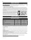
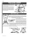
SPACERS
ELBOW
Do not allow the 3" flexible vent pipe to bunch
up on horizontal or vertical runs and elbows.
Keep it pulled tight. A 1” air gap between the
3" and 5" flexible vent pipes all around is
required for safe operation. A spacer is
required at the start, middle and end of each
elbow to ensure this gap is maintained.
Spacers are attached to the 3" flexible vent
pipe at predetermined intervals to maintain a
1” air gap to the 5" flexible vent pipe. These
spacers must not be removed.
!
WARNING
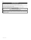
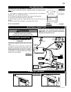
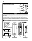
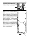
1. Fasten the roof support to the roof using the screws
provided. The roof support is optional. In this case the
venting is to be adequately supported using either
an alternate method suitable to the authority having
jurisdiction or the optional roof support. Figure 12.
2. Stretch the 3" fl ex vent pipe to the required length.
Slip the 3" fl ex vent pipe a minimum of 2” over the inner
pipe of the air terminal connector and secure with 3 #8
screws. Seal using a heavy bead of high temperature
sealant W573-0007 (not supplied). Figure 13.
NOTE: If using pipe clamps to connect vent
components, 3 screws must also be used to ensure the connection cannot slip off.
3. Repeat using the 5" fl ex vent pipe, using a heavy bead of high temperature sealant
W573-0002 (not supplied). Figure 13.
ROOF SUPPORT
FIGURE 12
3” FLEXIBLE
VENT PIPE
5” FLEXIBLE
VENT PIPE
INNER
PIPE
HIGH
TEMPERATURE
SEALANT
AIR
TERMINAL
CONNECTOR
FIGURE 13
VERTICAL AIR TERMINAL INSTALLATION