


26
W415-0580 / C / 04.07.08
Purge all gas lines with the glass door of the fireplace
removed. Assure that a continuous gas flow is at the burner
before installing the door.
TURN OFF THE GAS AND ELECTRICAL POWER BEFORE
SERVICING THE FIREPLACE.
CAUTION: Label all wires prior to disconnection when servic-
ing controls. Wiring errors can cause improper and dangerous
operation. Verify proper operation after servicing. This fi replace
and its venting system should be inspected before use and at least
annually by a qualifi ed service person. The fi replace area must
be kept clear and free of combustible materials, gasoline or other
fl ammable vapors and liquids. The fl ow of combustion and ventila-
tion air must not be obstructed.
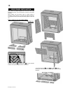
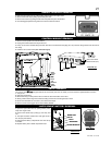
1. In order to properly clean the burner and pilot assembly, remove
the logs to expose both assemblies.
2. Keep the control compartment, logs, burner, air shutter opening
and the area surrounding the logs clean by vacuuming or brush-
ing, at least once a year.
3. Check to see that all burner ports are burning. Clean out any of
the ports which may not be burning or are not burning properly.
4. Check to see that the pilot fl ame is large enough to engulf the
thermocouple and thermopile and reaches toward the burner
with the third jet.
5. Replace the cleaned logs.
6. Check to see that the main burner ignites completely on all
openings when the gas knob for the burner is turned on. A 5 to
10 second total light-up period is satisfactory. If ignition takes
longer, consult your Authorized dealer / distributor.
7. Check that the gasket on the sides, top and bottom of the door
is not broken or missing. Replace if necessary.
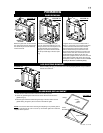
8. If for any reason the vent air intake system is disassembled,
re-install and re-seal per the instructions provided for the initial
installation
.
MAINTENANCE
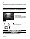
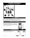
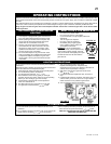
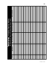
3/8” - 1/2”
PILOT
BURNER
THERMOCOUPLE
THERMOPILE
FLAME MUST ENVELOP
UPPER 3/8” TO 1/2” OF
THERMOCOUPLE AND
THERMOPILE
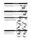
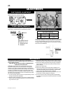
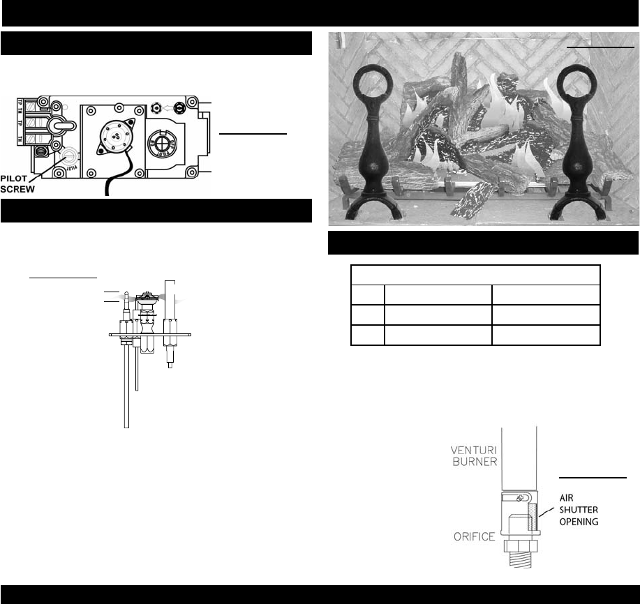
Closing the air shutter will cause a more yellow fl ame, but can lead
to carboning. Opening the air shutter will cause a more blue fl ame,
but can cause fl ame lifting from the burner ports. The fl ame may
not appear yellow immediately; allow 15 to 30 minutes for the fi nal
fl ame color to be established.
FIGURE 67
FIGURE 59
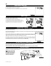
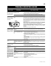
Adjust the pilot screw to provide properly sized fl ame. Turn in a
clockwise direction to reduce the gas fl ow.
FIGURE 68
ADJUSTMENTS
PILOT BURNER ADJUSTMENT
VENTURI ADJUSTMENT
Air Shutter Openings
Front Rear
LP 3/8” 7/16”
NG 5/32” 3/16”
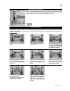
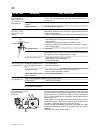
FLAME CHARACTERISTICS
It’s important to periodically perform a visual check of the pilot and
burner fl ames. Compare them to the illustrations provided.
FIGURE 70
FIGURE 69