


21
W415-0580 / C / 04.07.08
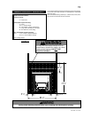
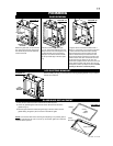
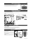
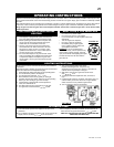
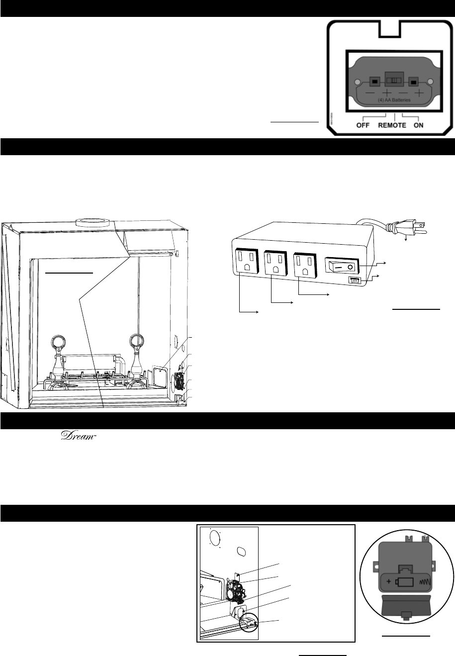
RECEIVER
SLOT
SPARK
MODULE
VALVE
WING
NUT
INNER
ACCESS
PANEL
1. Remove access panel from inside the fi rebox.
2. Unplug the control module from the junction box
3. Pull up on the control module being held down with velcro and disconnect the plugs (fan, aux). Remove wiring harness from the front of
the casing.
4. Install the new control module (see schematic Pg.16).
CONTROL MODULE REMOVAL
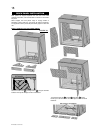
The valve on The is piped with two fl ex connectors (one inlet, one outlet). It can be removed or pulled forward for service.
1. Turn gas off.
2. Open right control door.
3. Remove the wing nut and pivot the valve out from the slot at the bottom of the valve.
4. Slowly pull the valve through the control door being careful not to kink the gas lines or wires.
5. Disconnect inlet/outlet fl ex connectors, wires and thermocouple.
6. Remove screws securing gas valve to the mounting bracket.
VALVE REMOVAL
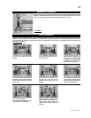
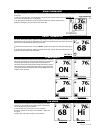
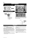
1. Open the right control door by pulling bottom portion away from magnet catch.
2. Remove the hearth strip by lifting up and away from unit.
3. Remove the receiver by pulling the left side of the plate away from the bracket.
4. Once disengaged pull the wiring harness out from the back of receiver.
FIGURE 44
REMOTE RECEIVER REMOVAL
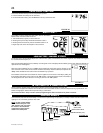
“AUTO SPARK” BATTERY REMOVAL
1. Open the right control door by pulling bottom portion
away from magnet catch.
2. Remove the hearth strip by lifting up and away from
unit.
3. The spark module is located in the front right corner of
the unit (see photo below).
4. Disengage the battery compartment door from the top
of module.
5. Replace battery and re-install compartment door.
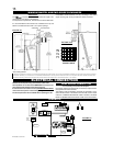
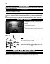
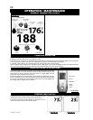
CONSTANTLY POWERED
120V OUTLET
FAN OUTLET
120V AUX OUTLET
MAINS VOLTAGE
SUPPLY CORD
MODULE ON/OFF SWITCH
COMMUNICATION BUS (3 PIN)
FIGURE 45
FIGURE 43
FIGURE 47
RECEIVER
SLOT
SPARK MODULE
VALVE
WING NUT
FIGURE 46