


20
W415-0580 / C / 04.07.08
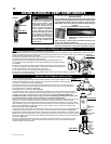
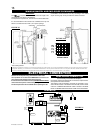
Randomly place the charcoal embers along the front and sides of the Hearth Panels in a realistic manner. Fine dust found in the
bottom of the bag should not be used.
Sprinkle vermiculite around the charcoal embers.
NOTE: Both charcoal embers and vermiculite are not to be placed on the burner.
Tear the embers into pieces and place along the front row of ports covering all of the burner area in front of the small logs (#2 &
#3). Care should be taken to shred the embers into thin, small irregular pieces as only the exposed edges of the fi bre hairs will
glow. The ember material will only glow when exposed to direct fl ame; however, care should be taken to not block the burner
ports.
Blocked burner ports can cause an incorrect fl ame pattern, carbon deposits and delayed ignition. phazer™ logs glow when
exposed to direct fl ame. Use only certifi ed “glowing embers” and phazer™ logs available from your Authorized dealer.
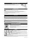
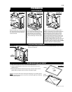
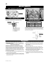
Your comes equipped with 2 “Night Lights™”. The lights
have been pre-wired and is controlled from the remote control.
If in the event the lamps or lens need replacing, follow these
instructions.
Shut off breaker at main power supply.
Remove the four screws that secure the lens frame to the Firebox
top.
This frame retains the glass lens. The lamp can now be accessed.
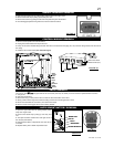
NIGHT LIGHT™ REPLACEMENT
NOTE: Do not handle the lamp (bulb) with bare fi ngers, protect with a clean
dry cloth.
The lamp will pull straight out of the socket. Replace with Wolf Steel parts only, as
lamp and lens are special “high temperature” products.
When re-installing, ensure integrity of gasket seal.
THE FIREBOX MUST BE SEALED.
Over tightening the screws could break the lens.
“Light Leakage” from the holes in the housing lamp may be observed. The
holes in the lamp housing are necessary for ventilation and must not be
covered.
FIGURE 42
GASKET
LENSE
FRAME
COLOURED SIDE UP
FIGURE 41
FIREBOX TOP
Night Lights
CHARCOAL EMBERS
GLOWING EMBERS
VERMICULITE
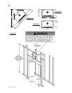
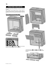
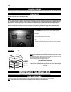
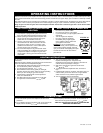
REMOTE AND VALVE ACCESS
Follow the door removal instructions. Remove the right side brick panel. Remove the four screws from the access panel.
NOTE: A new gasket will be required, when re-installing the access panel (see replacement parts).
INNER ACCESS PANEL
The control area can be accessed either through the control door or through the access panel inside the fi rebox.