


11
W415-0580 / C / 04.07.08
INSTALLATION / FRAMING
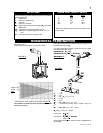
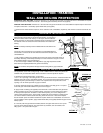
WALL AND CEILING PROTECTION
HORIZONTAL VENT SECTIONS: A minimum clearance of 2” all around the vent pipe on all horizontal runs to combustibles is required
except for clearances in fi replace enclosures**. Use fi restop spacer assembly W010-1797 (supplied).
VERTICAL VENT SECTIONS: A minimum of 1” all around the vent pipe on all vertical runs to combustibles is required except for clearances
in fi replace enclosures**. Use fi restop spacer W615-0075 (not supplied).
** Horizontal and vertical sections require 5” and 9” clearance from combustibles, respectively. See minimum enclosure clearances sec-
tion.
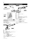
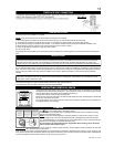
HORIZONTAL INSTALLATION
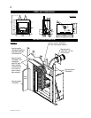
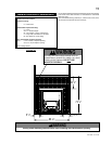
This application occurs when venting through an exterior wall. Having
determined the correct height for the air terminal location, cut and frame a
hole in the exterior wall 14 7/8” wide by 14 7/8” high to accommodate the
firestop assembly. Dry fit the firestop assembly before proceeding to ensure
the brackets on the rear surface fit to the inside surface of the horizontal
framing.
NOTE: The firestop assembly must be installed with the vent shield to the
top.
The length of the vent shield may be cut shorter for combustible walls that
are less than 8 1/2" thick but the vent shield must extend the full depth of the
combustible wall.
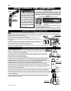
1. Apply a bead of caulking (not supplied) around the corner edge of the inside surface of
the firestop assembly, fit the firestop assembly to the hole and secure using the 4 screws
W415-0026 (supplied in your manual baggy).
2. Once the vent pipe is installed in its final position, apply high temperature sealant
W573-0007 (not supplied) between the pipe and the firestop.
NOTE: Do not fill the cavity between the pipe and the framing with any type of material.
14
7
/8”
DETERMINE
THE
CORRECT
HEIGHT
CAULKING
FIRESTOP
ASSEMBLY
VENT
SHIELD
FINISHING
MATERIAL
14
7
/8”
FIGURE 13
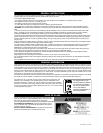
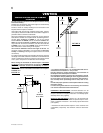
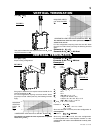
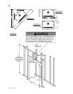
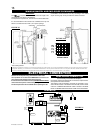
VERTICAL INSTALLATION
This application occurs when venting through a roof. Installation kits for various roof pitches are
available from your Authorized dealer. See Accessories to order the specific kit required.
1. Determine the air terminal location, cut and frame
141/2” x 141/2” openings in the ceiling and the roof to provide the minimum 2“ clearance between the
fireplace pipe / liner and any combustible material. Try to centre the exhaust pipe location midway
between two joist to prevent having to cut them. Use a plumb bob to line up the centre of the
openings. Do not fill this space with any type of material.
A
vent pipe shield will prevent any materials such as insulation, from filling up the 1” air space
around the pipe. Nail headers between the joist for extra support.
2. Apply a bead of caulking (not supplied) to the framework or to the Wolf Steel vent pipe shield
plate or equivalent (in the case of a finished ceiling), and secure over the opening in the ceiling.
A
firestop must be placed on the bottom of each framed opening in a roof or ceiling that the
venting system passes through. Apply a bead of caulking all around and place a firestop spacer
over the vent shield to restrict cold air from being drawn into the room or around the fireplace.
Ensure that both spacer and shield maintain the required clearance to combustibles. Once the vent
pipe is installed in its final position, apply sealant W573-0002 (not supplied) between the pipe and the
firestop spacer.
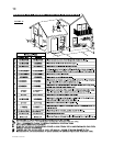
3. In the attic, after the pipe has been installed, slide the vent pipe collar down to cover up the
open end of the shield and tighten. This will prevent any materials, such as insulation, from
filling up the 1” air space around the pipe.
FIRESTOP
UNDERSIDE OF JOIST
14
1
/
2
”
14
1
/
2
”
CAULKING
VENT PIPE
SHIELD
HI-TEMP
SEALANT
2” OVERLAP
#8X1/2”
SELF DRILLING
SCREWS
FIGURE 14
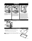
FIGURE 15
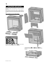
FIGURE 16