


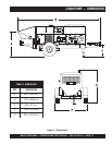
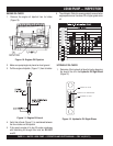
PAGE 20 — MAYCO LS600 PUMP — OPERATION AND PARTS MANUAL — REV. #4 (9/15/11)
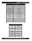
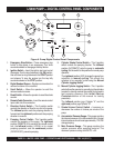
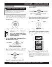
LS600 PUMP — DIGITAL CONTROL PANEL COMPONENTS
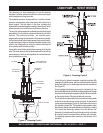
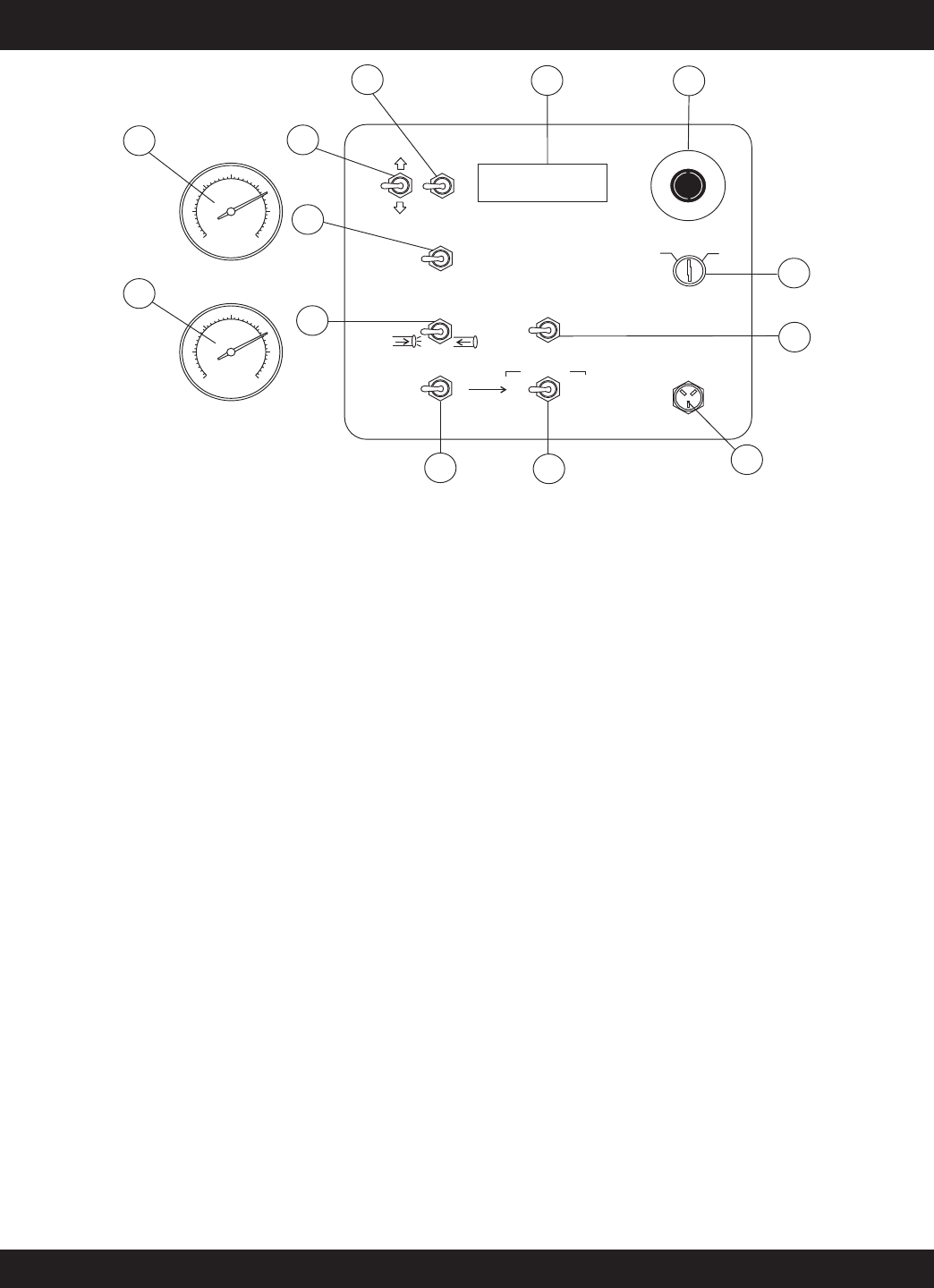
Figure 6. Pump Digital Control Panel Components
1. Emergency Stop Button – Press emergency stop
button to stop pump in an emergency. Turn knob
counterclockwise to disengage the stop button.
2. Ignition Switch – Insert the ignition key here to start
the engine. Turn the key clockwise to the ON position,
then continue turning clockwise to the START position
and release. To stop the engine turn the key fully
counterclockwise to the STOP position.
3. Digital Readout Screen – Displays and monitors the
various functions of the machine.
4. Scroll Switch – Allows the operator to scroll the
various readout screens.
5. Reset Switch – Allows the operator to reset the stroke
counter.
6. Remote Cable Connector – Insert the remote control
input cable into this connector.
7. Direction Control Switch – This 2-position switch
controls the direction of flow for any mix in the pump.
The
leftmost
position sets the pumping direction to
forward and the
rightmost
position sets the pumping
direction to reverse.
8. Pumping Control Switch – This 3-position switch
controls the pumping of the pump. The
rightmost
position (REMOTE) is for use with the remote control
unit, the
leftmost
position (LOCAL) is for normal
pumping operation, and the
centermost
position
(CENTER OFF) prevents pumping.
9. Cylinder Stroke Control Switch – This 2-position
switch controls the pumping function. The
leftmost
position (AUTOMATIC) sets the pump to
automatic
cycling
. Set the switch to this position for normal pump
operation.
The
rightmost
position (JOG) changes the pump from
automatic to
manual cycling
. This allows the
cylinders to be manually cycled using the
Manual
Cylinder Jogging Switch
.
10. Manual Cylinder Jogging Switch – This 2-position
switch allows the operator to manually jog the cylinders
to assist in clearing material line packs and is used to
test pumping pressure (See
Initial Start-up
Procedure
section of this manual for testing
procedure).
The
leftmost
position jogs Cylinder “A” and the
rightmost
position jogs Cylinder “B”.
11. Stroke Volume Control Switch – Increases or
decreases the number of strokes per minute of the
pump.
12. Accumulator Pressure Gauge – This gauge monitors
the internal pressure of the Accumulator tank. Normal
internal pressure should read approximately 1750 PSI
during pumping.
13. Main Pressure Gauge – This gauge monitors the
system pressure while pumping material. The
maximum pressure rating is 4400 PSI ± 50.
0
5
0
0
7
5
0
1
0
0
0
1
2
5
0
1
5
0
0
2
0
0
0
0
5
0
0
7
5
0
1
0
0
0
1
2
5
0
1
5
0
0
2
0
0
0
E
M
E
R
G
E
N
C
Y
S
T
O
P
ACCUMULATOR
PRESSURE
PUMPING
PRESSURE
1
2
4
5
6
10
9
7
3
8
12
11
13
OFF
ON
IGNITION
REMOTE
CONTROL
FLOW
DIRECTION
VOLUME
LOCAL
FORWARD
AUTOMATIC
JOG
RESET
SET
DECREASE
INCREASE
SCROLL
JOG “A”
CYLINDER STROKE
JOG “B”
REVERSE
CENTER
OFF
REMOTE
START