


MAYCO LS400/LS500 PUMP — OPERATION AND PARTS MANUAL — REV. #6 (09/19/11) — PAGE 43
LS400/LS500 PUMP — MAINTENANCE (PUMP)
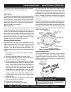
WHEEL BEARINGS
After every 6 months of operation inspect the wheel bearings.
Once a year, or when required, disassemble the wheel hubs
remove the old grease and repack the bearings forcing grease
between rollers, cone and cage with a good grade of high
speed wheel bearing greases (never use grease heavier than
265 A.S.T.M. penetration “No. 2.”).
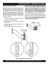
1. Fill the wheel hub with grease to the inside diameter of
the outer races and also fill the hub grease cap.
2. Reassemble the hub and mount the wheel. Then tighten
the adjusting nut, at the same time turn the wheel in
both directions, until there is a slight bind to be sure all
the bearing surfaces are in contact.
3. Back off the adjusting nut 1/6
to 1/4 turn or to the nearest
locking hole or sufficiently to allow the wheel to rotate
freely within limits of .001” to .010” end play. Lock the
nut at this position.
4. Install the cotter pin and dust cap, and tighten all
hardware.
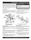
EXTENDED STORAGE INSTRUCTIONS
The following preventative maintenance is recommended
for extended periods of storage.
1. Check brake system for proper fluid level in master
cylinder and bleed all lines.
2. Lubricate all links and pivots to prevent any rusting.
3. Remove wheel and drum assemblies and spray a good
anti-corrosion compound (CRC formula 5-56) under rubber
boot on forward end of brake wheel cylinder. Avoid
spraying drum and brake lining.
4. Grease all bearings and reinstall wheel and drum
assemblies.
5. Make sure breakaway cable is fully released.
6. After extended storage, refer to the Maintenance Steps
listed above to insure that the trailer is ready for towing.
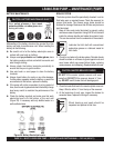
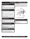
PRESSURE TEST
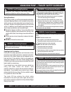
1. To determine the pressure of the Hydraulic System, set
the
Cylinder Stroke Control Switch
(Figure 42) to the
JOG position.
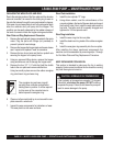
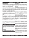
Figure 43. Manual Cylinder Jogging Switch
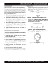
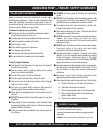
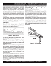
13. The Pumping Pressure Gauge (Figure 44) should read
approximately 4400 ± 50 PSI.
Figure 44. Pumping Pressure Gauge
2. Turn and hold the Manual Cylinder Jogging Switch
(Figure 43) to either JOG “A” or JOG “B” position to
test the pressure of that cylinder.
Figure 42. Cylinder Stroke Control Switch (JOG)