PAGE 30 — MAYCO LS400/LS500 PUMP — OPERATION AND PARTS MANUAL — REV. #6 (09/19/11)
LS400/LS500 PUMP — OPERATION
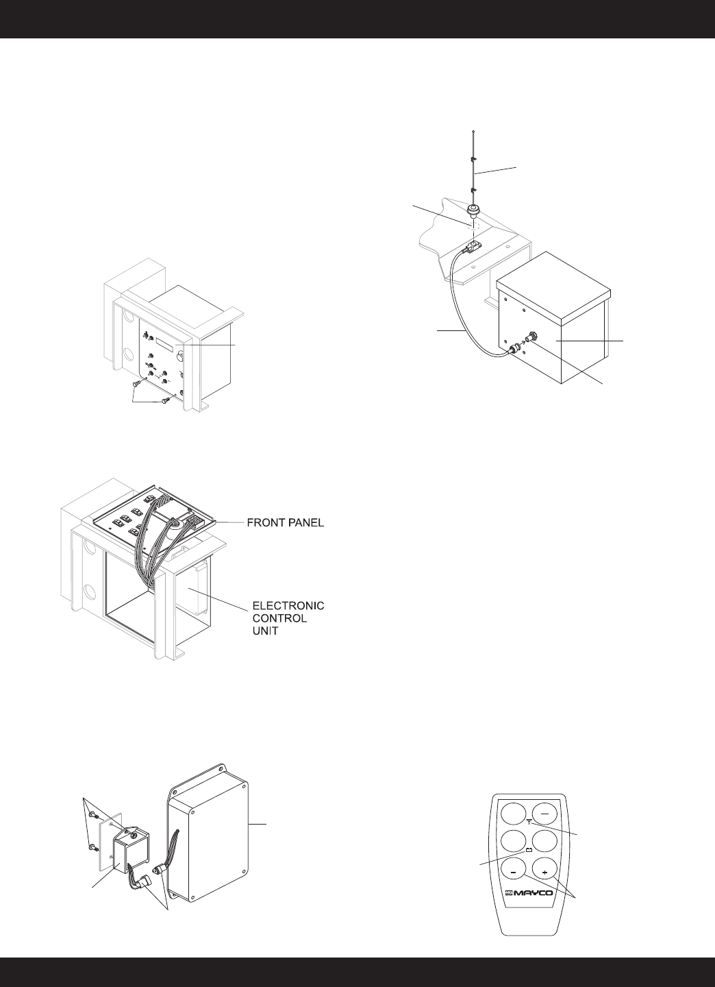
Figure 37. Radio Remote Control
REMOTE CONTROL (OPTIONAL)
The LS400/LS500 Concrete Pump has a remote control
feature that allows the pump to be remotely controlled. If
desired, the pump can be operated via a receiver/transmitter
(radio) or a hardwire method, which utilizes a 25-ft. extension
cable. Contact MQ Sales Department to order remote control.
Radio Remote Control
Installation of the Radio Remote Control Assembly
1. Remove the two screws on the digital control panel of
the pump. See Figure 33.
2. Tilt and slowly pull out the control panel and place on
top of box to gain access inside the box. See Figure 34.
3. Install the wireless remote module with the 2 screws
and nuts provided inside the control panel. Connect the
3-wire connector from the wireless remote module to
the electronic control unit. See Figure 35.
Radio Remote Control Buttons Operation
The pumping operation can be performed by radio remote
control (Figure 37). Before using remote control, move the
Pumping Control Switch on the control box to the REMOTE
position. The buttons on the remote control have the following
functions.
ON/OFF - Turns the power on or off. When power is on the
power LED lights red. If the battery LED turns red, 9V battery
needs to be replaced.
E-STOP - Turns off the pump completely in an emergency.
PUMP ON/OFF - Starts and stops the forward pumping.
PUMP REV - momentarily pumps in reverse direction.
VOLUME (+) - used to increase the pumping volume.
VOLUME (-) - used to decrease the pumping volume.
Figure 33. Removing Screws from Control Panel
E
M
E
R
G
E
N
C
Y
S
T
O
P
O
F
F
O
N
I
G
N
I
T
I
O
N
R
E
M
O
T
E
C
O
N
T
R
O
L
F
L
O
W
D
I
R
E
C
T
I
O
N
V
O
L
U
M
E
LOCAL
FO
R
WARD
A
U
TOM
A
TIC
JOG
RESET
SET
D
ECREA
SE
IN
CREASE
SCR
OLL
JOG“A”
C
YLINDE
RST
ROKE
JOG“B”
REVE
RSE
CENT
ER
OF
F
RE
MOT
E
S
T
A
R
T
REMOVE 2 SCREWS
CONTROL BOX
Figure 34. Pulling Out Control Panel
4. Reinstall the control panel and tighten the 2 screws.
5. On the top of the unit, to the right of the control box
(Figure 36), hammer out the knock-out hole and install
the remote antenna.
6. Connect the antenna cable to the connector on the rear
of the control box (Figure 36).
Figure 35. Installing Remote Control Module
Figure 36. Antenna Installation
ANTENNA
KNOCK-OUT
HOLE
ANTENNA
CONNECTOR
CABLE
CONTROL BOX
CONNECTOR
REAR OF
CONTROL BOX
SCREWSAND NUTS
WIRELESS
REMOTE
MODULE
CONNECTOR
ELECTRONIC
CONTROL
UNIT
E-STOP
ON
OFF
PUMP
REV
VOLUME VOLUME
PUMP
ON/OFF
POWER LED
NOTE: OLDER MODELS
MAYINDICATE
INSTEAD OF
FLOW
VOLUME
BATTERY LED


