


MAYCO LS400/LS500 PUMP — OPERATION AND PARTS MANUAL — REV. #6 (09/19/11) — PAGE 29
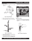
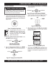
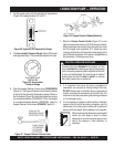
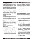
Figure 30. Accumulator
Pressure Gauge
5. The Accumulator Pressure Gauge (Figure 30) should
read approximately 1750 pounds per square inch (psi).
LS400/LS500 PUMP — OPERATION
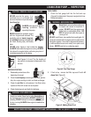
If hoses or lines are
blocked
for any reason, or if the
lines are
kinked
when starting up or during the pumping
cycle, the pump pressure could straighten out the kink
or force out the blockage. This rapid surge of material
could cause the lines to
whip
or
move
in a manner
that could cause injury to personnel.
CAUTION - HOSE/LINE BLOCKAGE
When pumping long distance or pumping stiff
mixes, you can expect a drop in volume
compared to shorter lines and wetter mixes
due to the change in valve efficiency or
cavitation.
8. It is important that once the slurry procedure is
completed, and concrete is flowing through the hose,
DO NOT stop the pour until all the slurry is pumped out
and the concrete has reached the end of the hose. The
only time to stop the pump during the priming procedure
is if a blockage occurs.
9. If it is necessary to replace or add a section of delivery
system, after the initial lubrication procedure, wet the
inside area of the hose, pipe or elbow with 5 gallons of
water per 25 foot length, before adding it to the system.
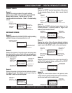
7. Slide the
Volume Control Switch
(Figure 27) to the
right to increase the volume to 25-30 strokes per minute.
Slowly discharge the concrete from the ready-mix truck
into the hopper and completely fill it. Keep the pump
running continuously until concrete is discharging at the
end of the delivery system. If the pump is stopped during
this procedure, a blockage may occur.
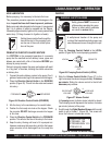
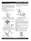
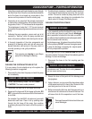
Figure 29. Hydraulic Oil Temperature Gauge
4. Let the pump cycle until the hydraulic oil temperature
(Figure 29) is approximately 50° to 60° F.
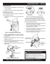
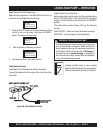
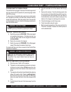
6. Push the Hopper Remixer Control Lever DOWNWARD
(Figure 31). The Hopper Remixer Control lever is located
to the left of the Hydraulic Temperature gauge. Observe
that the blades (Figure 32) inside the hopper are turning
in a clockwise direction (FORWARD). To turn the blades
in a counterclockwise direction (REVERSE), push the
Hopper Remixer Control lever UPWARD (Figure 31).
Figure 31. Hopper Remixer Control Lever
Figure 32. Hopper Remixer Blades (Rotation)
HYDRAULIC OIL
TEMPERATURE