


PAGE 28 — MAYCO LS400/LS500 PUMP — OPERATION AND PARTS MANUAL — REV. #6 (09/19/11)
HOSE LUBRICATION
Before pumping, it is necessary to lubricate the hose.
This procedure prevents separation and blockages in the
hose. Inspect the lines at all times to prevent problems.
Before concrete is discharged into the hopper, it is suggested
that 3 to 4 gallons of water be sprayed into the hopper,
followed by approximately 5 gallons of a creamy cement and
water slurry (1/2 bag of cement to 5 gallons of water).
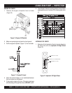
PRIMING THE PUMP WITH SLURRY MIXTURE
It is CRITICAL to the successful operation of a concrete
pump that the manifold and all delivery hoses, pipes and
elbows are coated with a film of lubrication BEFORE you
attempt to pump concrete.
Failure to properly prepare the pump and system will result
in a “dry pack” of concrete, blocking the shuttle valve tube
or delivery line.
1. Connect the entire delivery system to the pump. Pour 5
gallons of water and a bag of raw cement into the hopper.
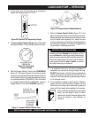
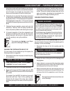
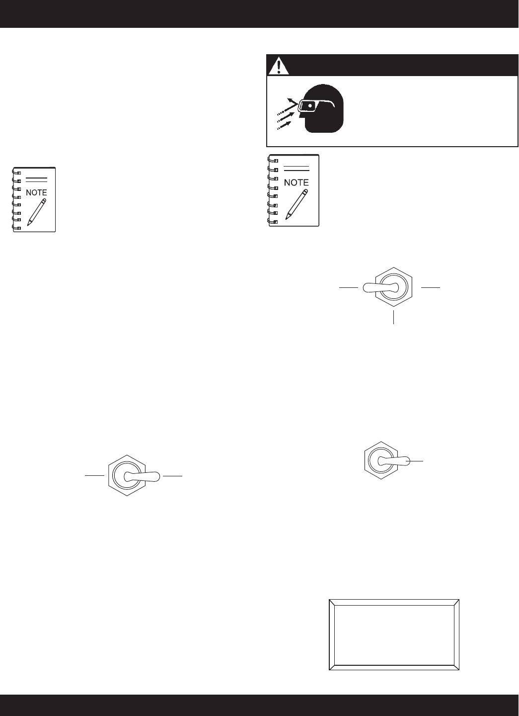
2. Place the
Direction Control Switch
to the REVERSE
position (Figure 25). This will mix the water and cement
into slurry.
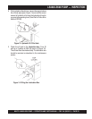
3. Mix the slurry to the consistency of a smooth batter.
4. Position the first ready-mix truck at the hopper. Check
the concrete. DO NOT discharge concrete into hopper
at this time.
5. Place the
Direction Control Switch
in the FORWARD
position. This will start the flow of the slurry to the hoses.
6. Keep the slurry flowing until most of it is pumped out.
However, make sure that some slurry is left on the hopper
when concrete is first discharged from the ready-mix
truck.
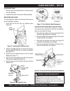
LS400/LS500 PUMP — OPERATION
Getting the concrete to flow through the
hose at the start of the pumping cycle
can be one of the most critical opera-
tions of the pour.
PUMPING
FORWARD
REVERSE
Figure 25. Direction Control Switch (REVERSE)
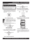
A
thumping
sound (cylinder stroke) should be heard.
The thumping sound represents the number of strokes
per minute (volume) of the pump.
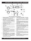
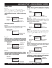
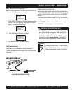
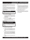
3. Scroll through the
Digital Readout Screen
with the scroll
switch to go to Screen 7 (Figure 28). This screen will
show the volume in strokes per minute.
2. Slide the
Volume Control Switch
(Figure 27) to the
right to increase the volume to approximately 10 strokes
per minute. Sliding the volume control to the left will
decrease
pump volume.
Figure 27. Volume Control
INCREASE
VOLUME
DECREASE
VOLUME
+
_
THROTTLE ON
STROKES: 100
STROKES/MIN 10.0
YDS/HR 0.0
7
Figure 28. Strokes Per Minute Display
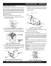
1. Place the
Pumping Control Switch
to the LOCAL
position (Figure 26) for normal pumping operation.
LOCAL
REMOTE
CENTER
OFF
Figure 26. Pumping Control Switch (LOCAL)
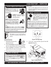
Safety glasses MUST be worn at
all times when operating the pump.
Failure to follow safety guidelines
can result in
serious
injury.
WARNING - SAFETY GLASSES
A well-planned location of the pump and
routing of the hose before starting a pour may
save subsequent moves throughout the job.