


PAGE 4 — MAYCO LS400/LS500 PUMP — OPERATION AND PARTS MANUAL — REV. #6 (09/19/11)
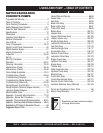
LS400/LS500 PUMP —TABLE OF CONTENTS
Specification and part number are subject
to change without notice.
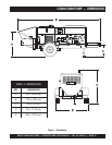
MAYCO LS400/LS500
CONCRETE PUMPS
Proposition 65 Warning ............................................. 2
Table of Contents ...................................................... 4
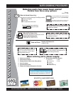
Parts Ordering Procedures ...................................... 5
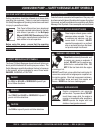
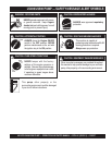
Safety Message Alert Symbols ..............................6-7
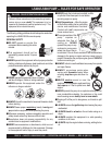
Rules for Safe Operation .....................................8-10
Specifications .......................................................... 12
Dimensions ............................................................. 13
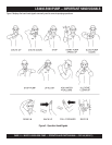
Important Hand Signals .......................................... 14
General Information ...........................................15-16
How it Works ........................................................... 17
Pump Components ............................................18-19
Digital Control Panel Components .......................... 20
Digital Readout Screen ........................................... 21
Engine Components ............................................... 22
Inspection ...........................................................23-25
Set-Up ..................................................................... 26
Start-Up Procedure ................................................. 27
Operation ...........................................................28-31
Pumping Information ..........................................32-35
Maintenance (Pump) .........................................36-43
Maintenance (Trailer) .........................................44-46
Trailer Safety Guidelines .................................... 47-61
Troubleshooting (Pump).....................................62-64
Troubleshooting (Engine) ........................................ 65
Troubleshooting (Brake System)............................. 66
Troubleshooting (Electrical) ...............................67-69
Wiring Diagram (Control Box) ............................70-73
Wiring Diagram (Optional Hopper Vibrator) ............ 74
Hydraulic System Diagram ..................................... 75
Manifold Block Ports ............................................... 76
Appendix - Concrete Mix Information ................77-78
Appendix - Slump Test Procedure........................... 79
Appendix - Recommended Shotcrete System ...... 80-81
Appendix - Recommended Shotcrete Accessories .... 82-83
Explanation Of Codes In Remarks Column ............ 84
Suggested Spare Parts ........................................... 85
COMPONENT DRACOMPONENT DRA
COMPONENT DRACOMPONENT DRA
COMPONENT DRA
WINGSWINGS
WINGSWINGS
WINGS
Name Plate and Decals ..................................... 86-89
Frame Assy. ....................................................... 90-91
Axle Assy. ........................................................... 92-93
Brake Line Assy. ................................................ 94-95
Brake Lights Assy............................................... 96-97
Trailer Hitch Assy................................................ 98-99
Battery Assy. .................................................. 100-101
Hopper Assy. .................................................. 102-103
Hopper Attachment Assy. .............................. 104-105
Hopper Interior Assy. ..................................... 106-107
Shuttle Cylinder Assy. .................................... 108-109
Lubrication Pistons Assy. ............................... 110-111
Fuel Tank Assy. .............................................. 112-115
Heat Exchanger Assy. .................................... 116-117
Accumulator Assy........................................... 118-119
Remixer Control Assy..................................... 120-121
Lubrication Panel Assy. .................................. 122-123
Engine Cover Assy. ........................................ 124-125
Hydraulic Tank Assy. ...................................... 126-127
Engine Assy. ................................................... 128-129
Throttle Assy. ................................................. 130-131
Water Separator Assy. ................................... 132-133
Hydraulic Pump Assy. .................................... 134-135
Manifold Assy. ................................................ 136-137
Control Box Assy. ........................................... 138-139
Control Box Harness Assy. ............................ 140-141
Remote Control Cable Assy. .......................... 142-143
Hydraulic Stabilizer Assy. (Optional) .............. 144-145
Terms and Conditions of Sale - Parts ................... 146
Mayco Pump Warranty .......................................... 147