


9
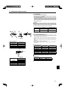
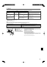
5) Assigning a remote controller to each unit
Each unit can be operated only by the assigned remote controller.
Make sure each pair of an indoor unit PC board and a remote controller is assigned
to the same pair No.
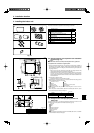
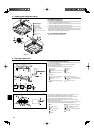
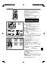
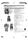
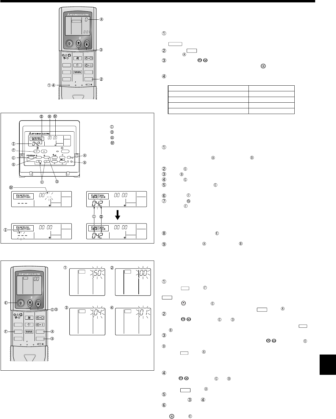
6) Wireless remote controller pair number setting operation (Fig. 6-8)
Press the SET button with something sharp at the end.
Start this operation from the status of remote controller display turned off.
blinks and Model No. is lighted.
Press the
min
button twice continuously.
Pair No.
“0” blinks.
Press the temp
buttons to set the pair number you want to set.
If you mistook the operation, press the ON/OFF
button and operate again
from procedure 2.
Press the SET button with something sharp at the end.
Set pair number is lighted for three seconds then turned off.
A Pair No. of wireless remote controller Indoor PC board
0 Factory setting
1 Cut J41
2 Cut J42
3-9 Cut J41, J42
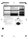
6. Electrical work
6.3. Function settings
6.3.1. Function setting on the unit (Selecting the unit functions)
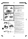
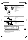
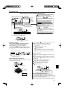
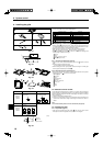
1) For wired remote controller (Fig. 6-9)
Changing the power voltage setting
• Be sure to change the power voltage setting depending on the voltage used.
Go to the function setting mode.
Switch OFF the remote controller.
Press the FILTER and TEST RUN
buttons simultaneously and
hold them for at least 2 seconds. FUNCTION will start to blink.
Use the buttons to set the refrigerant address (3) to 00.
Press
button and [--] will start to blink in the unit number (4) display.
Use the buttons to set the unit number (4) to 00.
Press the MODE button to designate the refrigerant address/unit number. [--]
will blink in the mode number (1) display momentarily.
Press the buttons to set the mode number (1) to 04.
Press the button and the current set setting number (2) will blink.
Use the
button to switch the setting number in response to the power supply
voltage to be used.
Power supply voltage
230 V : setting number = 1
208 V : setting number = 2
Press the MODE button and mode and the setting number (1) and (2) will
change to being on constantly and the contents of the setting can be confi rmed.
Press the FILTER and TEST RUN buttons simultaneously for at least two
seconds. The function selection screen will disappear momentarily and the air
conditioner OFF display will appear.
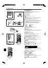
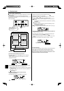
2) For wireless remote controller (Fig. 6-10)
Changing the power voltage setting
• Be sure to change the power voltage setting depending on the voltage used.
Going to the function select mode
Press the
CHECK
button twice continuously.
(Start this operation from the status of remote controller display turned off.)
CHECK
is lighted and “00” blinks.
Press the
temp button once to set “50”. Direct the wireless remote controller
toward the receiver of the indoor unit and press the
h
button .
Setting the unit number
Press the
temp buttons and to set the unit number “00”. Direct the wire-
less remote controller toward the receiver of the indoor unit and press the
min
but-
ton .
Selecting a mode
Enter 04 to change the power voltage setting using the
temp buttons and
. Direct the wireless remote controller toward the receiver of the indoor unit and
press the
h
button .
Current setting number: 1 = 1 beep (one second)
2 = 2 beeps (one second each)
3 = 3 beeps (one second each)
Selecting the setting number
Use the
temp buttons and to change the power voltage setting to 01 (240
V). Direct the wireless remote controller toward the sensor of the indoor unit and
press the
h
button .
To select multiple functions continuously
Repeat steps
and to change multiple function settings continuously.
Complete function selection
Direct the wireless remote controller toward the sensor of the indoor unit and press
the
button .
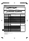
Note: Whenever changes are made to the function settings after installation
or maintenance, be sure to record the changes with a mark in the “Setting”
column of the Function table.
6.3.2. Function setting on the remote controller
Refer to the indoor unit operation manual.
Fig. 6-9
CHECK
CHECK
ON/OFF TEMP
FAN
VANE
TEST RUN
AUTO STOP
AUTO START
h
min
LOUVER
MODE
CHECK
RESETSET CLOCK
CHECK
Fig. 6-10
CHECKCHECK
Mode number
Setting number
Refrigerant address
Unit number
PAR-21MAA
ON/OFF
FILTER
CHECK
OPERATION
CLEAR
TEST
TEMP.
MENU
BACK DAY
MONITOR/SET
CLOCK
ON/OFF
Fig. 6-8
ON/OFF TEMP
FAN
VANE
TEST RUN
AUTO STOP
AUTO START
h
min
LOUVER
MODE
CHECK
RESETSET CLOCK
MODEL SELECT
MODEL SELECT