


8
6. Electrical work
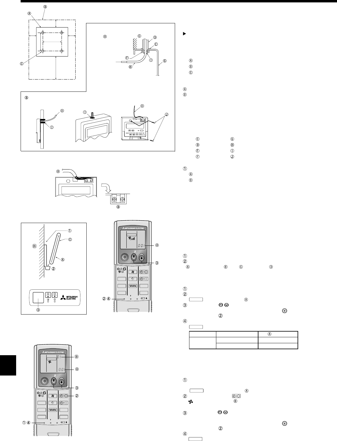
6.2. Remote controller
6.2.1. For wired remote controller
1) Installing procedures
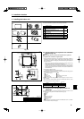
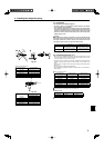
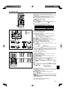
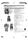
(1) Select an installing position for the remote controller. (Fig. 6-2)
The temperature sensors are located on both remote controller and indoor unit.
Procure the following parts locally:
Two piece switch box
Thin copper conduit tube
Lock nuts and bushings
[Fig.6-2]
Remote controller profi le
Required clearances surrounding the remote controller
Installation pitch
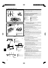
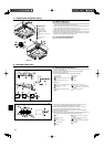
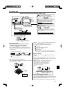
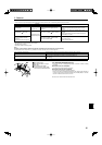
(2) Seal the service entrance for the remote controller cord with putty to prevent
possible invasion of dew drops, water, cockroaches or worms. (Fig. 6-3)
For installation in the switch box
For direct installation on the wall, select one of the following:
• Prepare a hole through the wall to pass the remote controller cord (in order to run
the remote controller cord from the back), then seal the hole with putty.
• Run the remote controller cord through the cut-out upper case, then seal the cut-
out notch with putty.
B-1. To lead the remote controller cord from the back of the controller
B-2. To run the remote controller cord through the upper portion
[Fig.6-3]
Wall Switch box
Conduit Remote controller cord
Lock nut
Seal with putty
Bushing Wood screw
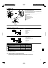
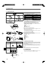
2) Connecting procedures (Fig. 6-4)
Connect the remote controller cord to the terminal block.
To TB5 on the indoor unit
TB6 (No polarity)
3) Two remote controllers setting
If two remote controllers are connected, set one to “Main” and the other to “Sub”.
For setting procedures, refer to “Function selection of remote controller” in the op-
eration manual for the indoor unit.
6.2.2. For wireless remote controller
1) Installation area
• Area in which the remote controller is not exposed to direct sunshine.
• Area in which there is no nearby heating source.
• Area in which the remote controller is not exposed to cold (or hot) winds.
• Area in which the remote controller can be operated easily.
• Area in which the remote controller is beyond the reach of children.
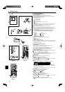
2) Installation method (Fig. 6-5)
Attach the remote controller holder to the desired location using two tapping screws.
Place the lower end of the controller into the holder.
Remote controller Wall Display panel Receiver
• The signal can travel up to approximately 7 meters (in a straight line) within 45
degrees to both right and left of the center line of the receiver.
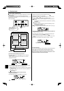
3) Setting (Fig. 6-6)
Insert batteries.
Press the SET button with something sharp at the end.
MODEL SELECT
blinks and Model No. is lighted.
Press the temp
buttons to set the Model No.
If you mistook the operation, press the ON/OFF
button and operate again
from procedure .
Press the SET button with something sharp at the end.
MODEL SELECT
and Model No. are lighted for three seconds, then turned off.
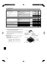
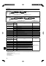
Indoor Outdoor Model No.
PLA
heat pump models 001
cooling only models 033
4)Automatic fan speed setting (For wireless remote controller) (Fig. 6-7)
It is necessary to set for wireless remote controller only when automatic fan
speed is not set at default setting.
It is not necessary to set for wired remote controller with automatic fan speed at
default setting.
Press the SET button with something sharp at the end.
Operate when display of remote controller is off.
MODEL SELECT
blinks and Model No. is lighted.
Press the AUTO STOP
button.
blinks and setting No. is lighted.
(Setting No.01: without automatic fan speed )
Press the temp.
buttons to set the setting No.02.
(Setting No.02:with automatic fan speed )
If you mistook the operation, press the ON/OFF button and operate again
from procedure .
Press the SET button with something sharp at the end.
MODEL SELECT
and Model No. are lighted for 3 seconds, then turned off.
ON/OFF TEMP
RESETSET CLOCK
MODEL SELECT
FAN
VANE
TEST RUN
AUTO STOP
AUTO START
h
min
LOUVER
MODE
CHECK
Fig. 6-6
ON/OFF TEMP
RESETSET CLOCK
MODEL SELECT
FAN
VANE
TEST RUN
AUTO STOP
AUTO START
h
min
LOUVER
MODE
CHECK
Fig. 6-7
1-3/161-3/16
1-3/16
4-23/32
3-9/32
B-1. B-2.
Fig. 6-3
BTB
Fig. 6-2
Fig. 6-4
Fig. 6-5
1-37/64
A6