


3
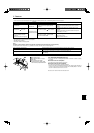
2. Installation location
Refer to the outdoor unit installation manual.
3. Installing the indoor unit
Fig. 3-1
Fig. 3-2
Fig. 3-3
5-29/32
6-5/16
6-5/16
6-5/16
6-5/16
3-17/32
33-27/32 to 35-13/16
(5/16)(5/16)
25/32 to 1-25/32 25/32 to 1-25/32
(inch)
25/32 to
1-25/32
25/32 to
1-25/32
31-7/8
37-3/8
33-1/16
7-3/8
33-1/16
5-5/16
11/16
+3/16
0
11/16
+3/16
0
*
1-15/16
to 2-3/4
*
4-1/8
1-3/8
C
D
Min. 98-7/16
Min. 19-11/16
(mm, inch)
Models
A
A12, A18, A24, A30 80, 3-5/32
A36, A42 85, 3-11/32
B
74, 2-29/32
77, 3-1/32
15/16
3-17/32
A
B
*
6-11/16
*
5-1/2
*
7-15/32
2-3/8
11-3/16 14-27/32
23-13/16
-3/16
+1-3/8
33-27/32 to 35-13/16
37-3/8
24-13/32
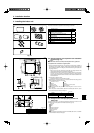
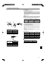
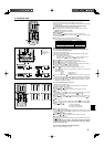
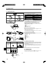
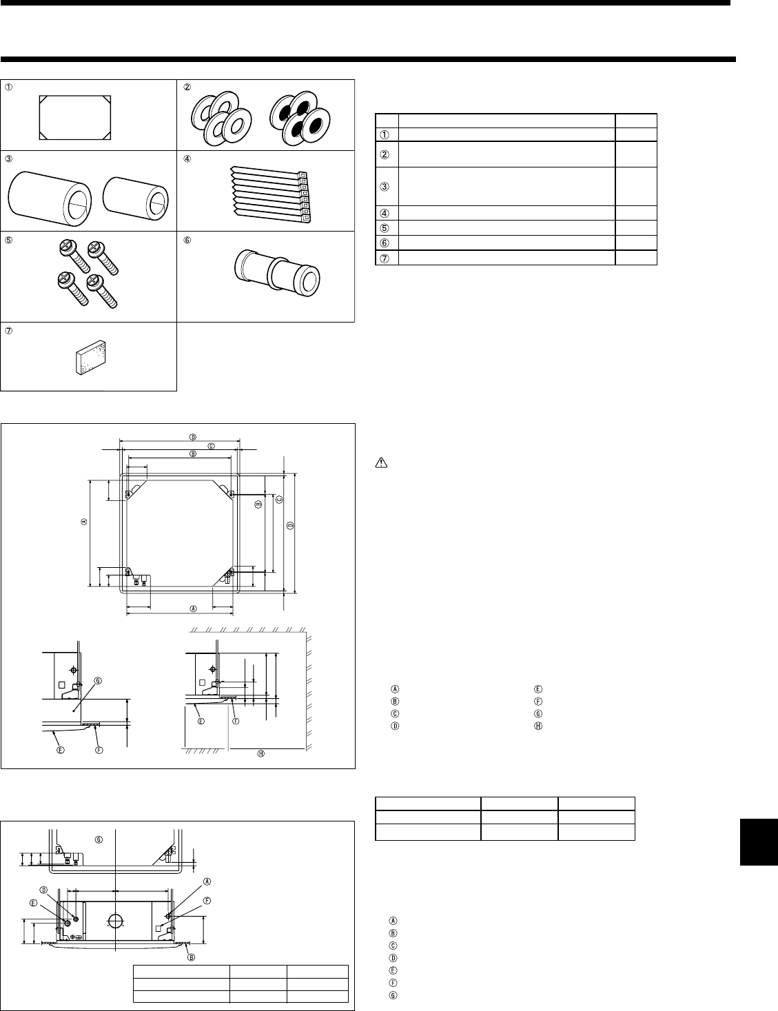
3.1. Check the indoor unit accessories (Fig. 3-1)
The indoor unit should be supplied with the following accessories.
Accessory name Q'ty
Installation template 1
Washers (with insulation)
Washers (without insulation)
4
4
Pipe cover (for refrigerant piping joint)
Small diameter
Large diameter
1
1
Band 8
Screw with washer (M5 × 25) for mounting grille 4
Drain socket 1
Insulation 1
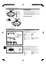
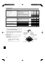
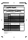
3.2. Ceiling openings and suspension bolt installation
locations (Fig. 3-2)
Caution:
Install the indoor unit at least 2.4m (94-1/2inch) above fl oor or grade level.
For appliances not accessible to the general public.
• Using the installation template (top of the package) and the gauge (supplied as
an accessory with the grille), make an opening in the ceiling so that the main unit
can be installed as shown in the diagram. (The method for using the template and
the gauge is shown.)
* Before using, check the dimensions of template and gauge, because they
change due to fl uctuations of temperature and humidity.
* The dimensions of ceiling opening can be regulated within the range shown
in Fig.3-2; so center the main unit against the opening of ceiling, ensuring
that the respective opposite sides on all sides of the clearance between them
becomes identical.
• Use M10 (3/8") suspension bolts.
* Suspension bolts are to be procured at the fi eld.
• Install securely, ensuring that there is no clearance between the ceiling panel &
grille, and between the main unit & grille.
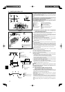
Outer side of main unit Grille
Bolt pitch
Ceiling
Ceiling opening Multi function casement (option)
Outer side of Grille
Entire periphery
* Note that the space between ceiling panel of the unit and ceiling slab, etc. must be 10 to 15 mm,
25/64 to 19/32 inch.
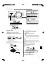
*
When the optional multi-functional casement is installed, add 135 mm, 5-5/16
inch to the dimensions marked on the fi gure.
(mm, inch)
Models C D
A12, A18, A24, A30 241, 9-1/2" 258, 10-3/16"
A36, A42 281, 11-1/16" 298, 11-3/4"
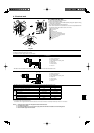
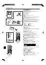
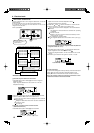
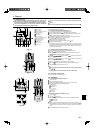
3.3. Refrigerant and drainage piping locations of
indoor unit
The fi gure marked with * in the drawing represent the dimensions of the main unit
excluding those of the optional multi function casement. (Fig. 3-3)
Drain pipe
Ceiling
Grille
Refrigerant pipe (liquid)
Refrigerant pipe (gas)
Water supply inlet
Main unit
*
When the optional multi-functional casement is installed, add 135 mm, 5-5/16inch
to the dimensions marked on the fi gure.