


7
6. Electrical work
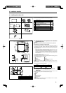
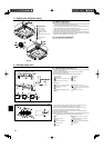
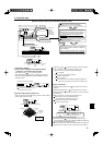
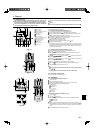
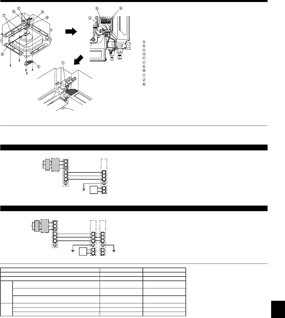
6.1. Indoor unit (Fig. 6-1)
1. Remove the electrical wiring service panel.
2. Remove the electrical box cover.
3. Wire the power cable and control cable separately through the respective wiring
entries given in the diagram.
• Do not allow slackening of the terminal screws.
• Leave excess cable so that the electrical box cover can be suspended below the
unit during servicing. (Approx. 50 to 100 mm, 2 to 4 inch)
Entry for control cable
Entry for power
Clamp
Electrical box cover
Service panel for electrical wiring
Temporary hook for
electrical box cover
Indoor / Outdoor unit connecting terminals
Remote controller connector
Secure with the clamp
Earth terminal
Conduit
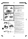
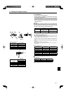
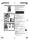
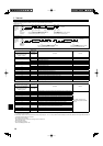
6.1.1. Indoor unit power supplied from outdoor unit
The following connection patterns are available.
The outdoor unit power supply patterns vary on models.
1 System
S1
S2
L
N
1
2
S1
S2
S3
S3
ABC
D
E
F
G
S1
S2
L
N
1
2
S1
S2
S3
1
2
S1
S2
S3
S3
ABC
D
E
F
GG
E
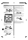
* Affi x label A that is included with the manuals near each wiring diagram for the indoor and outdoor units.
A Outdoor unit power supply
B Earth leakage breaker
C Wiring circuit breaker or isolating switch
D Outdoor unit
E Indoor unit earth
F Remote controller
G Indoor unit
* Affi x label A that is included with the manuals near each wiring diagram for the indoor and outdoor units.
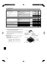
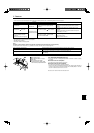
Indoor unit model PLA-A12, 18, 24, 30 PLA-A36, 42
Minimum circuit ampacity 1A 2A
Maximum rating of overcurrent protective device 15A 15A
Wiring
Wire No. × size
Indoor unit-Outdoor unit *1 3 × AWG16 (polar) 3 × AWG16 (polar)
Indoor unit earth 1 × Min. AWG16 1 × Min. AWG16
Remote contoroller-Indoor unit *2 2 × AWG22 (Non-polar) 2 × AWG22 (Non-polar)
Circuit
rating
Indoor unit-Outdoor unit S1-S2 *3 AC 208/230 V AC 208/230 V
Indoor unit-Outdoor unit S2-S3 *3 DC24 V DC24 V
Remote controller-Indoor unit *3 DC12 V DC12 V
*1. Max. 50 m, 165 ft
*2. The 10m, 30 ft wire is attached in the remote controller accessory. Max. 500 m, 1500ft
*3. The fi gures are NOT always against the ground.
S3 terminal has DC 24 V against S2 terminal. However between S3 and S1, these terminals are not electrically insulated by the transformer or other device.
Notes: 1. Wiring size must comply with the applicable local and national code.
2.
Use copper supply wires.
3. Use wires rated 300V or more for the power supply cables and the indoor unit/outdoor unit connecting cables.
4. Install an earth longer than other cables.
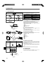
A Outdoor unit power supply
B Earth leakage breaker
C Wiring circuit breaker or isolating switch
D Outdoor unit
E Indoor unit earth
F Remote controller
G Indoor unit
Simultaneous twin system
1:1 System
Fig. 6-1