


16
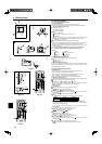
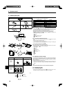
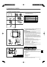
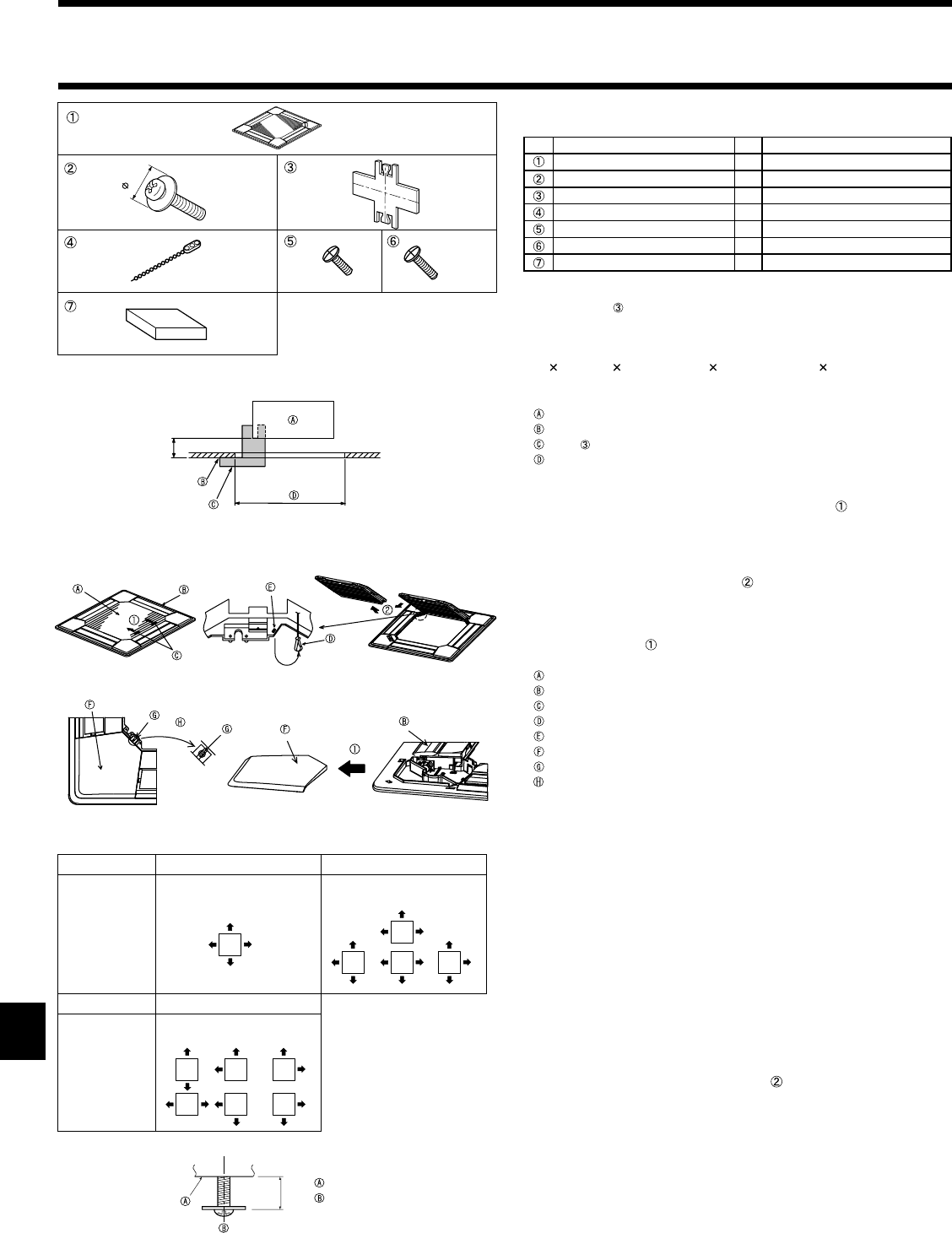
9.1. Checking the contents (Fig. 9-1)
• This kit contains this manual and the following parts.
Accessory name Q’ty Remarks
Grille 1
950 × 950 (mm), 37-3/8 × 37-3/8 (inch)
Screw with captive washer 4 M5 × 0.8 × 25
Gauge 1 (Divided into four parts)
Fastener 3
Screw 4 4 × 8
Screw 1 4 × 12
Wired remote controller 1 for PLP-42BAMD
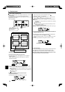
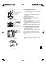
9.2. Preparing to attach the grille (Fig. 9-2)
• With the gauge supplied with this kit, adjust and check the positioning of the
unit relative to the ceiling. If the unit is not properly positioned relative to the ceil-
ing, it may allow air leaks or cause condensation to collect.
• Make sure that the opening in the ceiling is within the following tolerances:
860
860 - 910 910 mm, 33-7/8 33-7/8 to 35-13/16 35-13/16 inch.
• Make sure that A is performed within 17-22 mm, 11/16-7/8 inch. Damage could
result by failing to adhere to this range.
Main unit
Ceiling
Gauge (inserted into the unit)
Ceiling opening dimensions
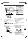
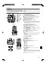
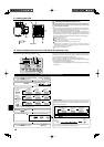
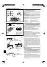
9.2.1. Removing the intake grille (Fig. 9-3)
• Slide the levers in the direction indicated by the arrows to open the intake
grille.
• Unlatch the hook that secures the grille.
* Do not unlatch the hook for the intake grille.
• With the intake grille in the “open” position, remove the hinge of the intake grille
from the grille as indicated by the arrows .
9.2.2. Removing the corner panel (Fig. 9-4)
• Remove the screw from the corner of the corner panel. Slide the corner panel as
indicated by the arrow
to remove the corner panel.
[Fig.9-3] [Fig.9-4]
Intake grille
Grille
Intake grille levers
Grille hook
Hole for the grille’s hook
Corner panel
Screw
Detail
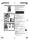
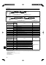
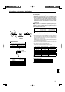
9.3. Selection of the air outlets
For this grille the discharge direction is available in 11 patterns. Also, by setting the
remote controller to the appropriate settings, you can adjust the air-fl ow and speed.
Select the required settings from the Table 1 according to the location in which you
want to install the unit.
1) Decide on the discharge direction pattern.
2) Be sure to set the remote contoller to the appropriate settings according to the
number of air outlets and the height of the ceiling on which the unit will be in-
stalled.
Note:
For 3 and 2-directional, please use the air outlet shutter plate (option).
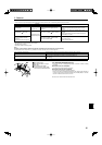
9.4. Installing the grille
9.4.1. Preparations (Fig. 9-5)
• Install the two enclosed screws with washer in the main unit (at the corner
drain pipe area and at the opposite corner) as shown in the diagram.
9. Installing the grille
8. System control
Refer to the outdoor unit installation manual.
Fig. 9-5
19/32 to 25/32
4-directional 3-directional
One pattern: 4 patterns:
Factory setting One air outlet fully closed
2-directional
6 patterns:
Two air outlet fully closed
Blowout
direction
patterns
Blowout
direction
patterns
20
Fig. 9-1
Fig. 9-2
A=11/16
+3/16
0
Fig. 9-3
Fig. 9-4
Main unit
Screw with
captive washer
Table 1
(inch)