


18
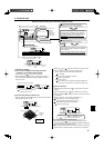
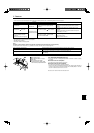
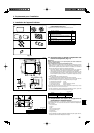
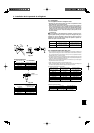
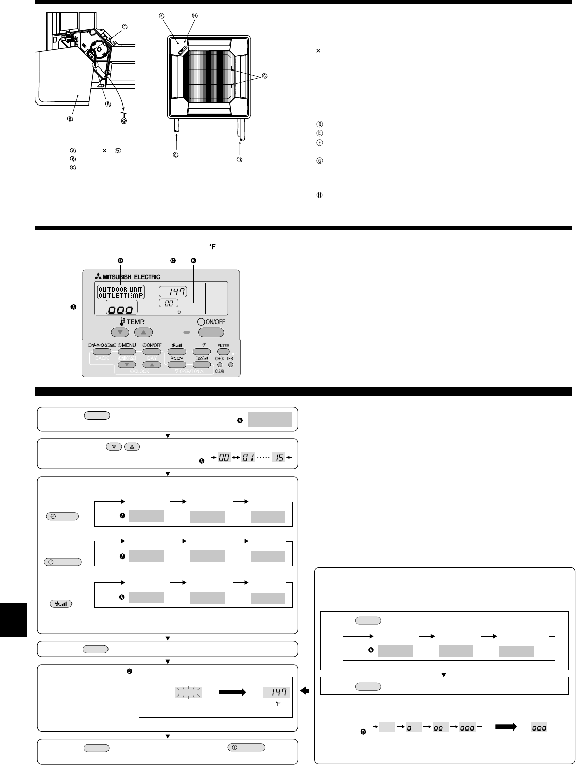
(1) Press the
TEST
button for three seconds to
activate the maintenance mode.
(2) Press the TEMP. buttons to set the refrigerant address.
MAINTENANCE
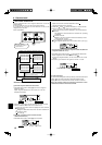
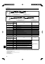
(3) Select the data you want to display.
MENU
ON/OFF
Compressor
information
COMP ON
x10 HOURS
COMP ON
x100 TIMES
COMP ON
CURRENT (A)
Cumulative
operation time
ON/OFF
number
Operation
current
Display
Display
Display
OUTDOOR UNIT
H•EXC. TEMP
OUTDOOR UNIT
OUTLET TEMP
OUTDOOR UNIT
OUTDOOR TEMP
Heat exchanger
temperature
Comp discharge
temperature
Outdoor ambient
temperature
Display
Outdoor unit
information
INDOOR UNIT
INLET TEMP
INDOOR UNIT
H•EXC. TEMP
INDOOR UNIT
FILTER USE H
Indoor room
temperature
Heat exchanger
temperature
Filter operation
time
Display
Indoor unit
information
* The filter operation time displayed is the number of hours the filter has been
used since the filter reset was performed.
(4) Press the
FILTER
button.
(5) The data is displayed in .
(Airflow temperature display example)
Blinking
Waiting for
response
Approx.
10 sec.
147
* Repeat steps (2) to (5) to check another data.
(6) Press the
TEST
button for three seconds or press the
ON/OFF
button to
deactivate the maintenance mode.
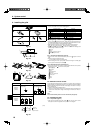
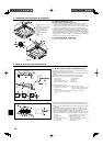
Stable operation
Using the maintenance mode, the operation frequency can be fixed and the op-
eration can be stabilized. If the air conditioner is stopped, use the following pro-
cedure to start this operation.
COOL
STABLE MODE
HEAT
STABLE MODE
STABLE MODE
CANCEL
Stable cooling
operation
Stable heating
operation
Stable operation
cancellation
Display
Press the
MODE
button to select the operation mode.
Press the
FILTER
button.
Waiting for
stable operation
Display
Stable
operation
10-20 min.
* You can check the data using steps (3) to (5) of the maintenance mode opera-
tion procedures while waiting for the stable operation.
Display example (Comp discharge temperature 147 )
Display
PAR-21MAA
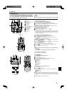
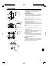
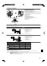
9. Installing the grille
Maintenance mode operation procedures
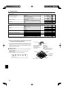
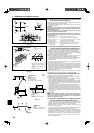
10. Easy maintenance function (For PUZ-A/PUY-A application only)
By using the maintenance mode, you can display many types of maintenance data
on the remote controller such as the heat exchanger temperature and compressor
current consumption for the indoor and outdoor units.
This function can be used whether the air conditioner is operating or not.
During air conditioner operation, data can be checked during either normal opera-
tion or maintenance mode stable operation.
* This function cannot be used during the test run.
* The availability of this function depends on the connecting outdoor unit. Refer to
the brochures.
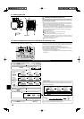
9.7. Installing the intake grille (Fig. 9-10 )
Note:
When reinstalling the corner panels (each with a safety wire attached), con-
nect the other end of each safety wire to the grille using a screw (4 pcs,
4
8) as shown in the illustration.
*If the corner panels are not attached, they may fall off while the unit is operating.
• Perform the procedure that is described in “9.2. Preparing to attach the grille” in
reverse order to install the intake grille and the corner panel.
• Multiple units can be installed with grille so that the position of the logo on each
corner panel is consistent with the other units regardless of the orientation of the
intake grille. Align the logo on the panel according to the wishes of the customer
as shown in the diagram to the left. (The position of the grille can be changed.)
Refrigerant piping of the main unit
Drain piping of the main unit
Position of the corner panel when sent from the factory (logo attached).
* Installation in any position is possible.
Position of the levers on the intake grille when sent from the factory.
* Although the clips can be installed in any of four positions, the confi guration shown here is
recommended.(It is not necessary to remove the intake grille when maintenance is performed
on the electric component box of the main unit.)
Receiver (Only PLP-42BALM Panel)
Screw (4ޓ8)ޓ
Corner panel
Safety wire
Fig. 9-10
(Enlarged)