


9
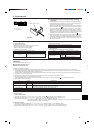
2 Wiring examples
• Controller name, symbol and allowable number of controllers.
2. M-NET Remote control cables
A : Power source
B : Transmission line
Name
Outdoor unit controller
Indoor unit controller
Remote controller
Symbol
OC
IC
RC
(M-NET)
MA
Allowable number of controllers
One to eight controllers for one OC
Maximum of 16 controllers for one
OC
Maximum of two per group
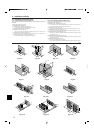
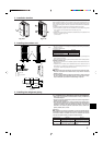
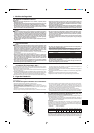
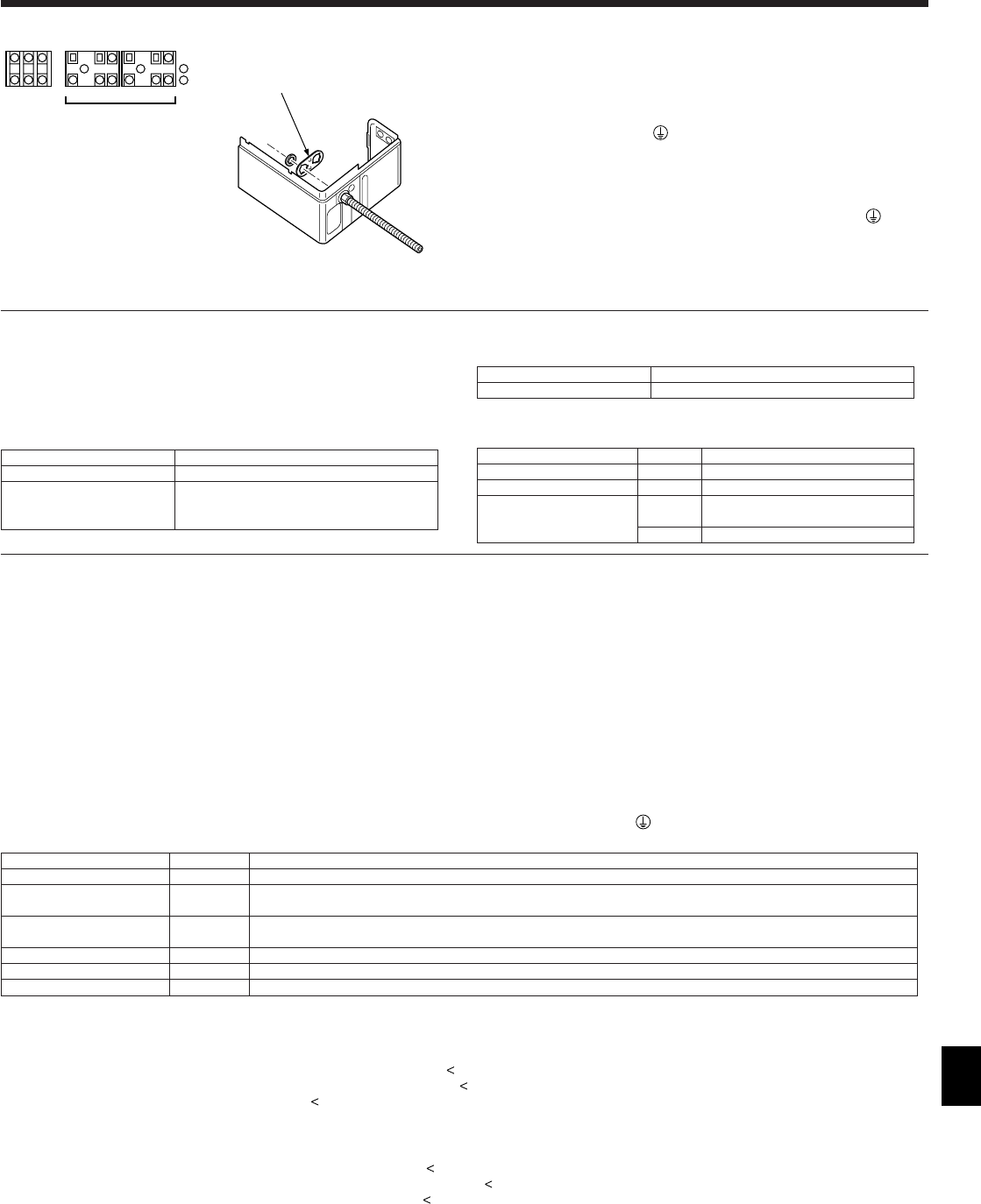
6.2. Control box and connecting position of wiring
(Fig. 6-1)
1. Connect the indoor unit transmission line to transmission terminal block (TB3), or
connect the wiring between outdoor units or the wiring with the centralized con-
trol system to the centralized control terminal block (TB7).
When using shielded wiring, connect shield ground of the indoor unit transmis-
sion line to the earth screw (
) and connect shield ground of the line between
outdoor units and the central control system transmission line to the shield (S)
terminal of the centralized control terminal block (TB7) shield (S) terminal. In
addition, in the case of outdoor units whose power supply connector CN41 has
been replaced by CN40, the shield terminal (S) of terminal block (TB7) of the
centralized control system should also be connected to the ground (
).
2. Conduit mounting plates (ø27 [1-1/16 inch]) are being provided. Pass the power
supply and transmission wires through the appropriate knock-out holes, then re-
move the knock-out piece from the bottom of the terminal box and connect the wires.
3. Fix power source wiring to terminal box by using buffer bushing for tensile force
(PG connection or the like).
6.3. Wiring transmission cables
1 Types of control cables
1. Wiring transmission cables
• Types of transmission cables: Shielding wire CVVS or CPEVS
• Cable diameter: More than 1.25 mm
2
[AWG16]
• Maximum wiring length: Within 200 m [656 ft]
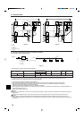
Fig. 6-1
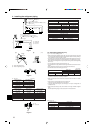
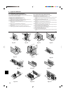
Example of a group operation system with multiple outdoor units (Shielding wires and address setting are
necessary.)
<Examples of Transmission Cable Wiring>
■ M-NET Remote Controller (Fig. 6-2)
■ MA Remote Controller (Fig. 6-3)
<Wiring Method and Address Settings>
a. Always use shielded wire when making connections between the outdoor unit (OC) and the indoor unit (IC), as well for all OC-OC, and IC-IC wiring intervals.
b. Use feed wiring to connect terminals M1 and M2 and the ground terminal on the transmission cable terminal block (TB3) of each outdoor unit (OC) to terminals M1, M2
and terminal S on the transmission cable block of the indoor unit (IC).
c. Connect terminals 1 (M1) and 2 (M2) on the transmission cable terminal block of the indoor unit (IC) that has the most recent address within the same group to the
terminal block on the remote controller (RC).
d. Connect together terminals M1, M2 and terminal S on the terminal block for central control (TB7) for the outdoor unit (OC).
e. The jumper connector CN41 on the control panel does not change.
f. Connect the terminal S on the terminal block for central control for the power supply unit to the ground terminal (
) in the electrical component box.
g. Set the address setting switch as follows.
Unit Range Setting Method
IC (Main) 01 to 50 Use the most recent address within the same group of indoor units
IC (Sub) 01 to 50
Use an address, other than that of the IC (Main) from among the units within the same group of indoor units. This must be
in sequence with the IC (Main)
Outdoor Unit 51 to 100
Use the most recent address of all the indoor units plus 50
* The address automatically becomes “100” if it is set as “01 - 50”.
M-NET R/C (Main) 101 to 150 Set at an IC (Main) address within the same group plus 100
M-NET R/C (Sub) 151 to 200 Set at an IC (Main) address within the same group plus 150
MA R/C – Unnecessary address setting (Necessary main/sub setting)
h. The group setting operations among the multiple indoor units is done by the remote controller (RC) after the electrical power has been turned on.
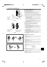
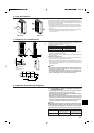
<Permissible Lengths>
1 M-NET Remote controller
• Max length via outdoor units: L
1+L2+L3+L4 and L1+L2+L3+L5 and L1+L2+L6+L7
=
500 m [1640 ft] (1.25 mm
2
[AWG16] or more)
• Max transmission cable length: L
1 and L3+L4 and L3+L5 and L6 and L2+L6 and L7
=
200 m [656 ft] (1.25 mm
2
[AWG16] or more)
• Remote controller cable length:r
1, r2, r2 +r3,r4
=
10 m [33 ft] (0.5 to 1.25 mm
2
[AWG20 to AWG16])
If the length exceeds 10 m [33 ft], use a 1.25 mm
2
[AWG16] shielded wire. The length of this section (L8) should be included in the
calculation of the maximum length and overall length.
2 MA Remote controller
• Max length via outdoor unit (M-NET cable): L
1+L2+L3+L4 and L1+L2+L6+L7
=
500 m [1640 ft] (1.25 mm
2
[AWG16] or more)
• Max transmission cable length (M-NET cable): L
1 and L3+L4 and L6 and L2+L6 and L7
=
200 m [656 ft] (1.25 mm
2
[AWG16]
or more)
• Remote controller cable length:c
1 and c1+c2 +c3 and c1+c2+c3+c4
=
200 m [656 ft] (0.3 to 1.25 mm
2
[AWG20 to AWG16])
6. Electrical work
M1
S
M2
A
B
M1
S
M2L1
L2
GR
TB3 TB7
Kind of remote control cable
Cable diameter
Remarks
Shielding wire MVVS
0.5 to 1.25 mm
2
[AWG20 to AWG16]
When 10 m [32 ft] is exceeded, use cable with
the same specifications as transmission line wir-
ing
3. MA Remote control cables
Kind of remote control cable
Cable diameter
2-core cable (unshielded)
0.3 mm
2
(AWG22) to 1.25 mm
2
(AWG16)
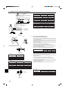
CONDUIT PLATE : accessory