


10
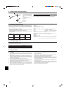
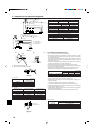
*1. A breaker with at least 3.0 mm [1/8 inch] contact separation in each poles shall be provided. Use non-fuse breaker (NF) or earth leakage breaker (NV).
*2. Use copper supply wires. Use the electric wires over the rating voltage 300 V.
1. Use a separate power supply for the outdoor unit and indoor unit.
2. Bear in mind ambient conditions (ambient temperature,direct sunlight, rain water,etc.) when proceeding with the wiring and connections.
3. The wire size is the minimum value for metal conduit wiring. The power cord size should be 1 rank thicker consideration of voltage drops.
Make sure the power-supply voltage does not drop more than 10%.
4. Specific wiring requirements should adhere to the wiring regulations of the region.
5. Power supply cords of parts of appliances for outdoor use shall not be lighter than polychloroprene sheathed flexible cord (design 60245 IEC57). For
example, use wiring such as YZW.
6. Install an earth longer than other cables.
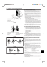
Warning:
• Be sure to use specified wires to connect so that no external force is imparted to terminal connections. If connections are not fixed firmly, it may cause
heating or fire.
• Be sure to use the appropriate type of overcurrent protection switch. Note that generated overcurrent may include some amount of direct current.
Caution:
• Some installation site may require attachment of an earth leakage breaker. If no earth leakage breaker is installed, it may cause an electric shock.
• Do not use anything other than breaker and fuse with correct capacity. Using fuse and wire or copper wire with too large capacity may cause a malfunction
of unit or fire.
30 A 30 mA 0.1 sec. or less30 A
5.3 [AWG10]5.3 [AWG10]
Indoor Unit
Main Cable*2
Minimum Wire Thickness
(mm
2
[AWG])
Breaker for Current
Leakage
Model
Outdoor Unit
P36, P48
Breaker for
Wiring*1
Ground
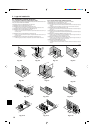
6. Electrical work
Thickness of Wire for Main Power Supply and On/Off Capacities
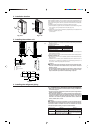
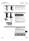
6.4. Wiring of main power supply and equipment capacity
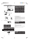
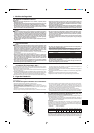
Schematic Drawing of Wiring (Example) (Fig. 6-4)
A : Switch (Breakers for Wiring and Current Leakage)
B : Outdoor Unit
C : Pull Box
D : Indoor Unit
Fig. 6-4
~/N (single), 60 Hz, 208/230 V
~/N (single), 60 Hz, 208/230 V
Power Supply
26 A
Minimum
circuit
ampacity
40 A
Maximum rating
of over current
protector device
Refer to installation manual of indoor unit.
A
B
~/N 208/230 V
GR
D D
C
A
D D
~/N 208/230 V
A
B
C
E
D
M1M2S
M1 M2 S
TB7
TB3
IC
(51)
M1 M2 S
TB5
RC
(01)
IC
M1 M2 S
TB5
(03)
IC
M1 M2 S
TB5
(02)
IC
M1 M2 S
TB5
(04)
IC
M1 M2 S
TB5
(05)
IC
M1 M2 S
TB5
(07)
IC
M1 M2 S
TB5
(06)
L2
L1
(101)
RC
(105)
RC
(104)
RC
(155)
OC
M1 M2 S
TB7
(53)
OC
r3
M1M2S
Power Supply
Unit
M1M2S
G-50A
L3
L6L7
L4
L5
r2
r4
r1
AB AB AB
AB
M1M2 S
TB3
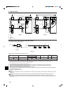
A
B
C
E
D
M1 M2 S
TB7
IC
(51)
M1 M2 12S
TB5 TB15
12
TB15
12
TB15
12
TB15
12
TB15
12
TB15
12
TB15
MA
(01)
IC
M1 M2 S
TB5
(03)
IC
M1 M2 S
TB5
(02)
IC
M1 M2 S
TB5
(04)
IC
M1 M2 S
TB5
(05)
IC
M1 M2 S
TB5
(07)
IC
M1 M2 S
TB5
(06)
L2
L1
MA
MA
MA
OC
M1 M2 S
TB7
(53)
OC
c1
c4
c3
S
Power Supply
Unit
S
G-50A
L3
L6L7
L4
c3
AB
AB
AB
M1M2
M1M2
c1
c1
c2 c2
AB
M1M2S
TB3
M1M2S
TB3
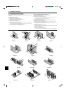
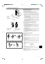
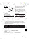
■ MA Remote Controller
Fig. 6-2 Fig. 6-3
A : Group 1
B : Group 3
C : Group 5
D : Shielded Wire
E : Sub Remote Controller
( ): Address
■ M-NET Remote Controller