


6
B
A
H
B C
L
r
d
a
h
b c
C
C
CC
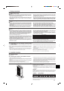
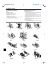
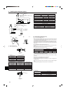
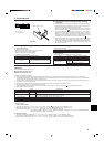
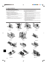
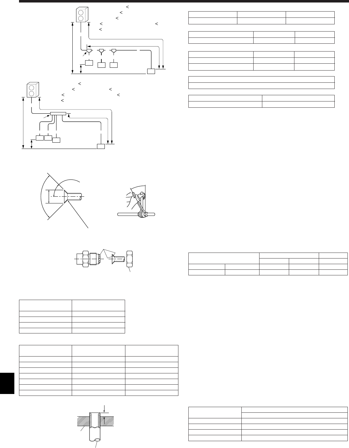
4.2. Connecting pipes (Fig. 4-2)
Fig. 4-1 is a sample of piping system.
• When commercially available copper pipes are used, wrap liquid and gas pipes
with commercially available insulation materials (heat-resistant to 100°C [212°F] or
more, thickness of 12 mm [1/2 inch] or more).
• The indoor parts of the drain pipe should be wrapped with polyethylene foam insu-
lation materials (specific gravity of 0.03, thickness of 9 mm [23/64 inch] or more).
• Apply thin layer of refrigerant oil to pipe and joint seating surface before tightening
flare nut. A
• Use two wrenches to tighten piping connections. B
• Use leak detector or soapy water to check for gas leaks after connections are com-
pleted.
• Apply refrigerating machine oil over the entire flare seat surface. C
• Use the flare nuts for the following pipe size. D
(mm [inch])
Indoor unit Outdoor unit
P06-P18 P24-P54 P48
Gas side Pipe size ø12.7 [1/2] ø15.88 [5/8] ø15.88 [5/8]
Liquid side Pipe size ø6.35 [3/8] ø9.52 [3/8] ø9.52 [3/8]
• When bending the pipes, be careful not to break them. Bend radius of 100 mm [3-
15/16 inch] to 150 mm [5-27/32 inch] is sufficient.
• Make sure the pipes do not contact the compressor. Abnormal noise or vibration
may result.
1 Pipes must be connected starting from the indoor unit.
Flare nuts must be tightened with a torque wrench.
2 Flare the liquid pipes and gas pipes and apply a thin layer of refrigeration oil
(Applied on site).
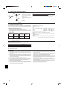
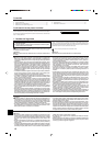
• When usual pipe sealing is used, refer to Table 1 for flaring of R410A refrigerant
pipes.
The size adjustment gauge can be used to confirm A measurements.
A (mm [inch])
Å Liquid pipe ı Gas pipe
PUMY ø9.52 [3/8] ø15.88 [5/8]
B, C, D (mm [inch])
Ç Total capacity of indoor units Å Liquid pipe ı Gas pipe
ø9.52 [3/8] ø15.88 [5/8]
a, b, c, d, e, f (mm [inch])
Î Model number Å Liquid pipe ı Gas pipe
P06, P08, P12, P15, P18 ø6.35 [1/4] ø12.7 [1/2]
P24, P30, P36, P48, P54 ø9.52 [3/8] ø15.88 [5/8]
‰ Branch kit model
CMY-Y62-G-E
Ï 4-Branching header Ì 8-Branching header
CMY-Y64-G-E CMY-Y68-G-E
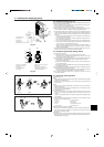
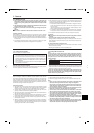
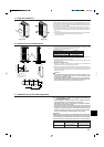
A Flare cutting dimensions
B Flare nut tightening torque
90° ±0.5°
øA
R0.4~R0.8
A
45°±2°
B
C
D
A Die
B Copper pipe
Fig. 4-2
A
A
B
Fig. 4-3
A (Fig. 4-2)
Copper pipe O.D. Flare dimensions
øA dimensions
ø6.35 [1/4] 8.7 - 9.1 [11/32-23/64]
ø9.52 [3/8] 12.8 - 13.2 [1/2-33/64]
ø12.7 [1/2] 16.2 - 16.6 [41/64-21/32]
ø15.88 [5/8] 19.3 - 19.7 [49/64-25/32]
Copper pipe O.D. Flare nut O.D. Tightening torque
(mm [inch]) (mm [inch]) (N·m [ft·lbs])
ø6.35 [1/4] 17 [43/64] 14 - 18 [10-13]
ø6.35 [1/4] 22 [7/8] 34 - 42 [25-30]
ø9.52 [3/8] 22 [7/8] 34 - 42 [25-30]
ø12.7 [1/2] 26 [1-3/64] 49 - 61 [35-44]
ø12.7 [1/2] 29 [1-9/64] 68 - 82 [49-59]
ø15.88 [5/8] 29 [1-9/64] 68 - 82 [49-59]
ø15.88 [5/8] 36 [1-27/64] 100 - 120 [71-87]
B (Fig. 4-2)
Copper pipe O.D. A (mm [inch])
(mm [inch]) Clutch type
ø6.35 [1/4] 1.0 - 1.5 [3/64-1/16]
ø9.52 [3/8] 1.0 - 1.5 [3/64-1/16]
ø12.7 [1/2] 1.0 - 1.5 [3/64-1/16]
ø15.88 [5/8] 1.0 - 1.5 [3/64-1/16]
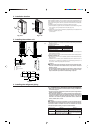
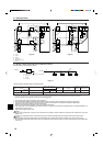
Table 1 (Fig. 4-3)
4. Installing the refrigerant piping
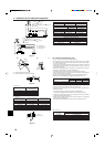
A : Outdoor Unit
B : First Branch
C : Indoor unit
A+B+C+a+b+c+d
=
120 m [394 ft]
L = A+B+C+d
=
80 m [262 ft]
R= B+C+d
=
30 m [100 ft]
H
=
30 m [100 ft] (Outdoor lower H
=
20 m [70 ft])
h
=
12 m [39 ft]
A+a+b+c+d
=
120 m [394 ft]
L = A+d
=
80 m [262 ft], R= d
=
30 m [100 ft]
H
=
30 m [100 ft] (Outdoor lower H
=
20 m [70 ft])
h
=
12 m [39 ft]
Fig. 4-1
(mm [inch])
(inch)
B
A
a
b
c
C
C
CC
d
H
h
L
r