


7
C
B
A
E
D
4. Installing the refrigerant piping
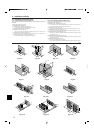
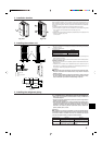
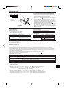
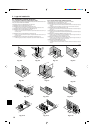
4.3. Refrigerant piping (Fig. 4-4)
Remove the service panel D (three screws) and the front piping cover A (two screws)
and rear piping cover B (two screws).
1 Perform refrigerant piping connections for the indoor/outdoor unit when the out-
door unit’s stop valve is completely closed.
2 Vacuum-purge air from the indoor unit and the connection piping.
3 After connecting the refrigerant pipes, check the connected pipes and the indoor
unit for gas leaks. (Refer to 4.4 Refrigerant pipe airtight testing method)
4 Vacuumize the refrigerant lines through the service port of the liquid and gas stop
valves. And then open the stop valves completely (for both the liquid and gas stop
valves). This will completely connect the refrigerant lines of the indoor and out-
door units.
• If the stop valves are left closed and the unit is operated, the compressor and
control valves will be damaged.
• Use a leak detector or soapy water to check for gas leaks at the pipe connec-
tion sections of the outdoor unit.
• Do not use the refrigerant from the unit to purge air from the refrigerant lines.
• After the valve work is completed, tighten the valve caps to the correct torque:
20 to 25 N·m [14 to 18 ft·lbs] (200 to 250 kgf·cm).
Failure to replace and tighten the caps may result in refrigerant leakage. In
addition, do not damage the insides of the valve caps as they act as a seal to
prevent refrigerant leakage.
5 Use sealant to seal the ends of the thermal insulation around the pipe connection
sections to prevent water from entering the thermal insulation.
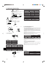
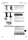
4.4. Refrigerant pipe airtight testing method
(1)Connect the testing tools.
• Make sure the stop valves A B are closed and do not open them.
• Add pressure to the refrigerant lines through the service port C of the liquid
stop valve A and the gas stop valve B.
(2) Do not add pressure to the specified pressure all at once; add pressure little by little.
1 Pressurize to 0.5 MPa [73 PSIG], wait five minutes, and make sure the
pressure does not decrease.
2 Pressurize to 1.5 MPa [218 PSIG], wait five minutes, and make sure the pres-
sure does not decrease.
3 Pressurize to 3.8 MPa [550 PSIG] and measure the surrounding temperature
and refrigerant pressure.
(3) If the specified pressure holds for about one day and does not decrease, the pipes
have passed the test and there are no leaks.
• If the surrounding temperature changes by 1°C [1.8°F], the pressure will change
by about 0.01 MPa [1.5 PSIG]. Make the necessary corrections.
(4)If the pressure decreases in steps (2) or (3), there is a gas leak. Look for the
source of the gas leak.
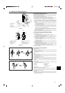
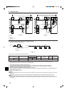
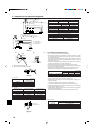
4.5. Stop valve opening method
(1)Gas side (Fig. 4-6)
Type A
1 Remove the cap, then turn one-quarter rotation counter-clockwise with a flat-bladed
screwdriver to complete open.
2 Check that the valves are fully open, then return the cap to its original state and
tighten it down.
Type B
1 Remove the cap, pull the handle toward you and rotate 1/4 turn in a counterclock-
wise direction to open.
2 Make sure that the stop valve is open completely, push in the handle and rotate
the cap back to its original position.
(2)Liquid side (Fig. 4-7)
1 Remove the cap and turn the valve rod counterclockwise as far as it will go with
the use of a 4 mm [5/32 inch] hexagonal wrench. Stop turning when it hits the
stopper.
(ø6.35 [1/4 inch]: Approximately 4.5 revolutions) (ø9.52 [3/8 inch]: Approximately
10 revolutions)
2 Make sure that the stop valve is open completely, push in the handle and rotate
the cap back to its original position.
A Valve
B Unit side
C Handle
D Cap
E Local pipe side
Fig. 4-5
Fig. 4-4
A Front piping cover
B Piping cover
C Stop valve
D Service panel
E Bend radius : 100 mm - 150 mm
A Stop valve <Liquid side>
B Stop valve <Gas side>
C Service port
D Open/Close section
E Local pipe
F Sealed, same way for gas side
G Pipe cover
H Do not use a wrench here.
Refrigerant leakage may result.
I Use two wrenches here.
A
B
H
I
C
D
E
F
G
C
(1)
Fig. 4-7
Fig. 4-6
B
G
H
E
D
I
(2) 1
2
E
G
G
A
B
C
D
F
A
B
J
D
E
G
Type A Type B
F Open position side
G Service port
H Wrench hole
I Refrigerant flow direction
J Operation section
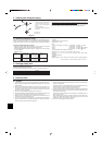
Refrigerant pipes are protectively wrapped
• The pipes can be protectively wrapped up to a diameter of ø90 mm [ø3-35/64 inch]
before or after connecting the pipes. Cut out the knockout in the pipe cover follow-
ing the groove and wrap the pipes.
Pipe inlet gap
• Use putty or sealant to seal the pipe inlet around the pipes so that no gaps remain.
(If the gaps are not closed, noise may be emitted or water and dust will enter the
unit and breakdown may result.)