


8
=+–
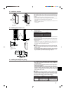
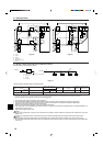
4.6. Additional refrigerant charge
Refrigerant of 3 kg [6.6 lbs] equivalent to 50 m [165 ft] total extended piping length is
already included when the outdoor unit is shipped. Thus, if the total extended piping
length is 50 m [165 ft] or less, there is no need to charge with additional refrigerant.
Calculation of Additional Refrigerant Charge
• If the total extended piping length exceeds 50 m [165 ft], calculate the required
additional refrigerant charge using the procedure shown below.
• If the calculated additional refrigerant charge is a negative amount, do not charge
with any refrigerant.
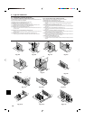
<Example>
(Please see the lower half of Fig. 4-1.)
Outdoor model : P48
Indoor
1: P24 A: ø9.52 [3/8"] 30 m [98 ft] a:ø9.52 [3/8"] 15 m [49 ft]
2: P15 b:ø6.35 [1/4"] 10 m [33 ft]
3: P08 c: ø6.35 [1/4"] 10 m [33 ft]
4: P06 d:ø6.35 [1/4"] 20 m [66 ft]
The total length of each liquid line is as follows
ø9.52 [3/8"] : A + a = 30 m + 15 m = 45 m [98 ft + 49 ft = 147 ft]
ø6.35 [1/4"] : b + c + d = 10 m + 10 m + 20 m = 40 m [33 ft + 33 ft + 66 ft = 132 ft]
Therefore,
<Calculation example>
Additional
refrigerant charge = 45 m × 0.06 kg + 40 m × 0.024 kg – 3.0 kg = 0.7 kg (rounded up)
= [147 ft × 0.041 lbs + 132 ft × 0.016 lbs – 6.6 lbs = 1.54 lbs]
4. Installing the refrigerant piping
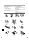
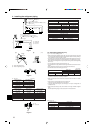
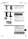
5. Drainage piping work
Outdoor unit drainage pipe connection
When drain piping is necessary, use the drain socket or the drain pan (option).
P36·P48
Drain socket PAC-SG61DS-E
Drain pan PAC-SG64DP-E
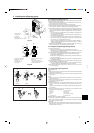
6.1. Caution
1 Follow ordinance of your governmental organization for technical standard re-
lated to electrical equipment, wiring regulations and guidance of each electric
power company.
2 Wiring for control (hereinafter referred to as transmission line) shall be (5 cm [2
inch] or more) apart from power source wiring so that it is not influenced by elec-
tric noise from power source wiring. (Do not insert transmission line and power
source wire in the same conduit.)
3 Be sure to provide designated grounding work to outdoor unit.
4 Give some allowance to wiring for electrical part box of indoor and outdoor units,
because the box is sometimes removed at the time of service work.
5 Never connect the main power source to terminal block of transmission line. If
connected, electrical parts will be burnt out.
6 Use 2-core shield cable for transmission line. If transmission lines of different
systems are wired with the same multiplecore cable, the resultant poor transmit-
ting and receiving will cause erroneous operations.
6. Electrical work
7 Only the transmission line specified should be connected to the terminal block for
outdoor unit transmission.
(Transmission line to be connected with indoor unit : Terminal block TB3 for trans-
mission line, Other : Terminal block TB7 for centralized control)
Erroneous connection does not allow the system to operate.
8 In case to connect with the upper class controller or to conduct group operation in
different refrigerant systems, the control line for transmission is required between
the outdoor units each other.
Connect this control line between the terminal blocks for centralized control. (2-
wire line with no polarity)
When conducting group operation in different refrigerant systems without con-
necting to the upper class controller, replace the insertion of the short circuit
connector from CN41 of one outdoor unit to CN40.
9 Group is set by operating the remote controller.
At the
conditions
below:
Refrigerant
amount for
outdoor unit
3.0 kg
[6.6 lbs]
Liquid pipe size
Total length of
ø6.35 × 0.024 kg
[1/4" × 0.016 lbs]
(m) × 0.024 (kg/m),
[ft] × 0.016 [lbs/ft]
Additional
refrigerant charge
kg
[lbs]
Liquid pipe size
Total length of
ø9.52 × 0.06 kg
[3/8" × 0.041 lbs]
(m) × 0.06 (kg/m),
[ft] × 0.041 [lbs/ft]
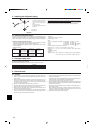
<Additional Charge>
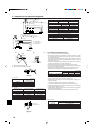
* The figure to the left is an example only.
The stop valve shape, service port po-
sition, etc., may vary according to the
model.
* Turn section A only.
(Do not further tighten sections A and
B together. )
C Charge hose
D Service port
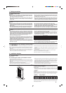
Precautions when using the charge valve (Fig.4-8)
Do not tighten the service port too much when installing it, otherwise, the valve core
could be deformed and become loose, causing a gas leak.
After positioning section B in the desired direction, turn section A only and tighten it.
Do not further tighten sections A and B together after tightening section A.
Fig. 4-8