


4
5-29/32
11-13/16
39-3/8
Max. 19-11/16
7-7/8
11-13/16
7-7/8
39-3/8
5-29/32
39-3/8
9-27/32
9-27/32
59-1/16
19-11/16
Max. 19-11/16
11-13/16
59-1/16
19-11/16
59-1/16
Max. 11-13/16
59-1/16
59-1/16
19-11/16
39-3/8
23-5/8
78-24/32
5-29/32
59-1/16
23-5/8
118-4/32
19-11/16
59-1/16
31-1/2
5-29/32
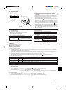
2. Installation location
Fig. 2-3
Fig. 2-7
Fig. 2-8
Fig. 2-9
Fig. 2-10 Fig. 2-11
Fig. 2-12 Fig. 2-13 Fig. 2-14
Fig. 2-6
Fig. 2-5Fig. 2-4Fig. 2-2
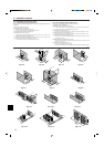
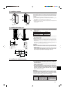
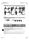
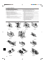
2.4. Ventilation and service space
2.4.1. When installing a single outdoor unit
Minimum dimensions are as follows, except for Max., meaning Maximum dimensions,
indicated.
Refer to the figures for each case.
1 Obstacles at rear only (Fig. 2-2)
2 Obstacles at rear and above only (Fig. 2-3)
• Do not install the optional air outlet guides for upward airflow.
3 Obstacles at rear and sides only (Fig. 2-4)
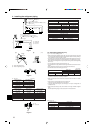
4 Obstacles at front only (Fig. 2-5)
∗ When using an optional air outlet guide, the clearance is 500 mm [19-11/16 inch] or more.
5 Obstacles at front and rear only (Fig. 2-6)
∗ When using an optional air outlet guide, the clearance is 500 mm [19-11/16 inch] or more.
6 Obstacles at rear, sides, and above only (Fig. 2-7)
• Do not install the optional air outlet guides for upward airflow.
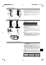
2.4.2. When installing multiple outdoor units
Leave 10 mm [13/32 inch] space or more between the units.
1 Obstacles at rear only (Fig. 2-8)
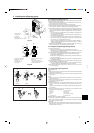
2 Obstacles at rear and above only (Fig. 2-9)
• No more than three units must be installed side by side. In addition, leave space as shown.
• Do not install the optional air outlet guides for upward airflow.
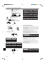
3 Obstacles at front only (Fig. 2-10)
∗ When using an optional air outlet guide, the clearance is 1000 mm [39-3/8 inch] or more.
4 Obstacles at front and rear only (Fig. 2-11)
∗ When using an optional air outlet guide, the clearance is 1000 mm [39-3/8 inch] or more.
5 Single parallel unit arrangement (Fig. 2-12)
∗ When using an optional air outlet guide installed for upward airflow, the clearance is 1000
mm [39-3/8 inch] or more.
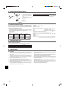
6 Multiple parallel unit arrangement (Fig. 2-13)
∗ When using an optional air outlet guide installed for upward airflow, the clearance is 1500
mm [59-1/16 inch] or more.
7 Stacked unit arrangement (Fig. 2-14)
• The units can be stacked up to two units high.
• No more than two stacked units must be installed side by side. In addition, leave space as shown.
(inch)