


74
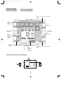
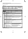
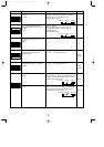
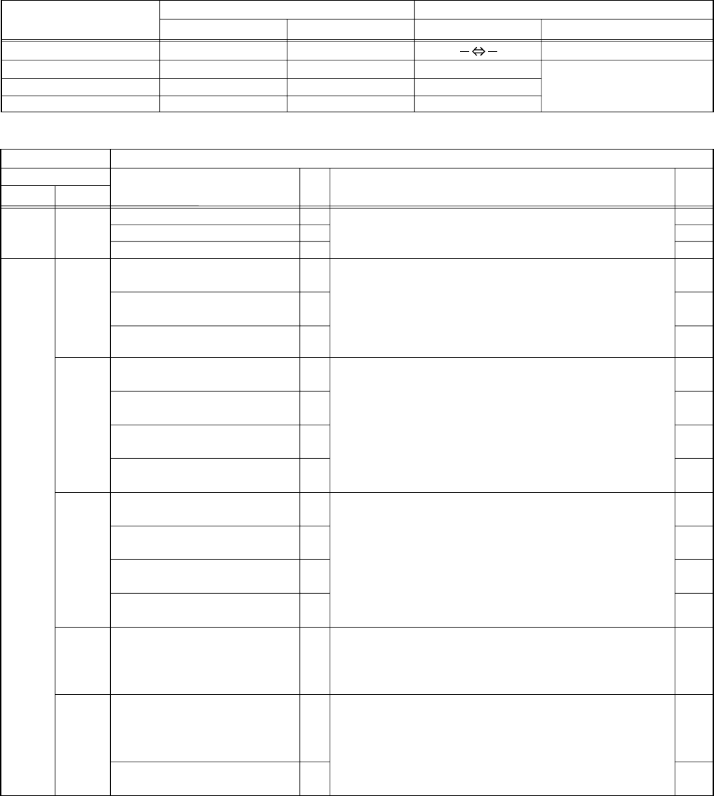
<Display function of inspection for outdoor unit>
The blinking patterns of both LED1(green) and LED2(red) indicate the types of abnormality when it occurs. Types of
abnormality can be indicated in details by connecting an optional part ‘A-Control Service Tool (PAC-SK52ST)’ to connector
CNM on outdoor controller board.
F3
F5
F9
—
—
—
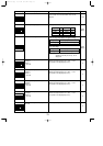
E6
E7
—
—
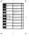
E0
E3
E4
E5
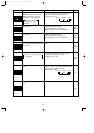
EF
Ed
A0~A8
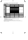
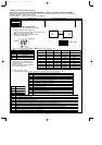
[Display]
(1)Normal condition
(2)Abnormal condition
Unit condition
Outdoor controller board A-Control Service Tool
LED1 (Green) LED2 (Red) Error code
When the power is turned on
When unit stops
When compressor is warming up
When unit operates
Lighted Lighted
Lighted
Lighted
Lighted
Not lighted
Indication of the display
Alternately blinking display
Operation mode
Not lighted
Lighted
00, etc.
08, etc.
C5, H7 etc.
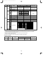
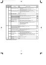
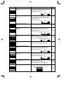
Indication Error
Error
code
w1
Outdoor controller board
Contents Inspection method
LED1 (Green) LED2 (Red)
1 blinking 2 blinking
2 blinking 1 blinking
2 blinking
3 blinking
4 blinking
5 blinking
Connector(63L) is open.
Connector(63H) is open.
2 connectors are open.
Startup time over
Error code is not defined.
Miswiring of indoor/outdoor unit conne-
cting wire, excessive number of indoor
units (4 units or more)
Miswiring of indoor/outdoor unit co-
nnecting wire (converse wiring or di-
sconnection)
Indoor/outdoor unit communication error
(signal receiving error) is detected by in-
door unit.
Indoor/outdoor unit communication error
(transmitting error) is detected by indoor
unit.
Indoor/outdoor unit communication error
(signal receiving error) is detected by
outdoor unit.
Indoor/outdoor unit communication error
(transmitting error) is detected by outdoor
unit.
Remote controller signal receiving
error is detected by remote controller.
Remote controller transmitting error
is detected by remote controller.
Remote controller signal receiving
error is detected by indoor unit.
Remote controller transmitting error
is detected by indoor unit.
Serial communication error
<Communication between outdoor
controller board and outdoor power
board>
<Communication between outdoor
controller board and M-NET P.C. board>
Communication error of M-NET
system
W1.Error code displayed on remote controller
W2.Refer to service manual for indoor unit.
1
Check if indoor/outdoor connecting wire is connected correctly.
2
Check if 4 or more indoor units are connected to outdoor unit.
3Check if noise entered into indoor/outdoor connecting wire
or power supply.
4Re-check error by turning off power, and on again.
1
Check if connector (63L or 63H) on the outdoor controller
board is not disconnected.
2
Check continuity of pressure switch (63L or 63H) by tester.
1
Check if connector (CN4) on outdoor controller board and
outdoor power board is not disconnected.
2
Check if there is poor connection of connector on outdoor
controller board(CNMNT and CNVMNT).
3
Check M-NET communication signal.
1Check if remote controller is MA remote controller(PAR-21MAA).
2Check if noise entered into transmission wire of remote controller.
3Check if noise entered into indoor/outdoor connecting wire.
4Re-check error by turning off power, and on again.
1Check if connecting wire of indoor unit or remote controller
is connected correctly.
2Check if noise entered into transmission wire of remote
controller.
3Re-check error by turning off power, and on again.
1
Check if indoor/outdoor connecting wire is connected correctly.
2
Check if noise entered into indoor/outdoor connecting wire or
power supply.
3
Check if noise entered into indoor/outdoor controller board.
4
Re-check error by turning off power, and on again.
P.35
P.36
P.36
P.36
(EA)
P.36
(Eb)
P.36
(EC)
w2
w2
P.41
(E8)
P.41
(E9)
P.40
P.41
P.40
P.41
P.41
P.41
P.42~
P.45
Detailed
reference
page
OCH429--3.qxp 07.11.20 9:19 AM Page 74