


25
9
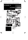
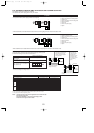
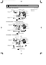
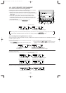
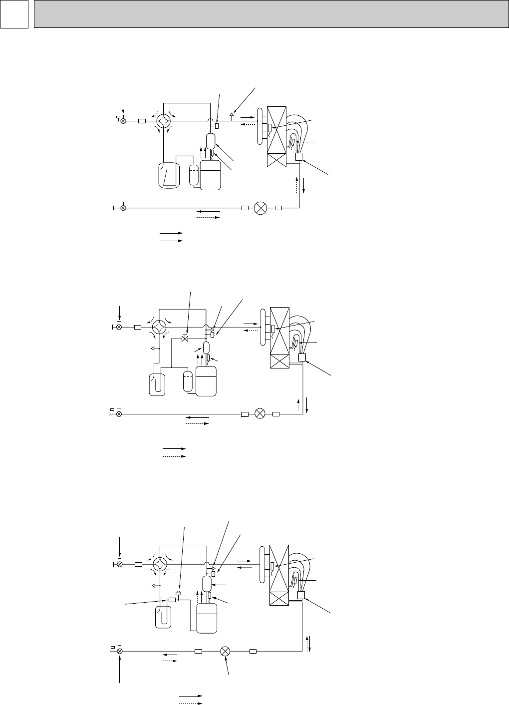
REFRIGERANT SYSTEM DIAGRAM
PUZ-A24/30/36NHA2 PUZ-A24/30/36NHA2-BS
Outdoor heat exchanger
Thermistor
(TH3)
Thermistor
(TH6)
Distributor
Service
port
(check)
Accumulator
Compressor
Refrigerant GAS pipe
15.88A({5/8)
Refrigerant LIQUID pipe
9.52A({3/8)
Stop valve
(with service port)
4-way valve
Service
port
(check)
High pressure
protect switch
Refrigerant flow in cooling
Refrigerant flow in heating
Linear expansion valve
Thermistor
(TH4)
Muffler
Ball valve
Bypass valve
(#50)
Strainer
(#100)
Strainer
(#100)
Strainer
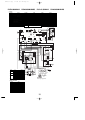
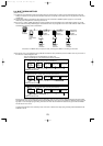
PUZ-A18NHA2 PUZ-A18NHA2-BS
Accumulator
Stop valve
(with service port)
Compressor
Refrigerant GAS pipe
12.7A({1/2)
Refrigerant LIQUID pipe
6.35A({1/4)
Stop valve
4-way valve
Service
port(check)
High pressure
protect switch
Outdoor heat exchanger
Thermistor
(TH3)
Thermistor
(TH6)
Distributor
Muffler
Thermistor(TH4)
Linear expansion valve
Refrigerant flow in cooling
Refrigerant flow in heating
(#50)
Strainer
(#100)
Strainer
(#100)
Strainer
<4-way valve solenoid coil>
Heating : ON
Cooling : OFF
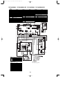
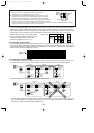
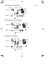
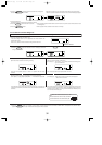
PUZ-A42NHA2 PUZ-A42NHA2-BS
Service
port
(check)
Accumulator
Compressor
Refrigerant GAS pipe
15.88A({5/8)
Refrigerant LIQUID pipe
9.52A({3/8)
4-way
valve
Service
port
(check)
High pressure protect switch
Linear expansion valve
Muffler
Thermistor
(TH4)
Refrigerant flow in cooling
Refrigerant flow in heating
Ball valve
(#50)
Strainer
Strainer
(#100)
Strainer
(#100)
Strainer
(#100)
Low pressure protect
switch
Stop valve
(with service port)
Outdoor heat exchanger
Thermistor
(TH3)
Thermistor
(TH6)
Distributor
Unit : mm(inch)
OCH429--1.qxp 07.11.20 9:17 AM Page 25